Aluminum alloy semi-solid slurry preparation device
A technology for semi-solid slurry and preparation device, which is used in stirring devices, lighting and heating equipment, furnaces, etc., can solve the problems of vortex and other problems, achieve the effect of stable liquid level, improved rotating torque, and reduction of intermediate links
- Summary
- Abstract
- Description
- Claims
- Application Information
AI Technical Summary
Problems solved by technology
Method used
Image
Examples
Embodiment 1
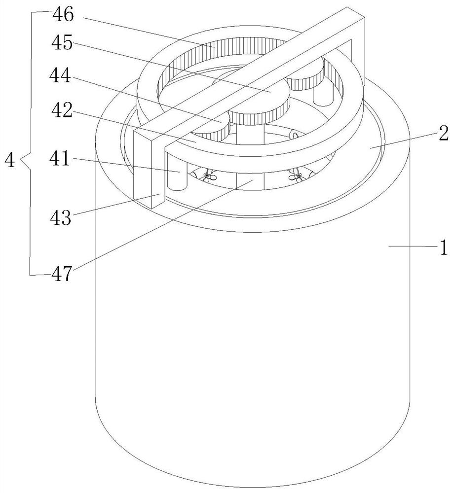
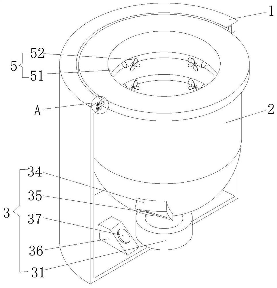
[0033] see Figure 1-6 , the present invention provides a technical solution: an aluminum alloy semi-solid slurry preparation device, including a protective shell 1, a crucible 2, a drive assembly 3 and a steady flow assembly 4, the crucible 2 is rotatably connected to the inside of the protective shell 1, and the crucible 2 The upper surface of the upper surface is flush with the upper surface of the protective shell 1, the driving assembly 3 is arranged between the bottom of the crucible 2 and the inner wall of the bottom of the protective casing 1, and the flow stabilization assembly 4 is arranged on the upper surface of the crucible 2;
[0034]Further, the drive assembly 3 includes a movable block 31, which is fixedly connected to the bottom inner wall of the protective shell 1, and the lower end of the crucible 2 is fixedly connected with a support ball 32, and the upper surface of the movable block 31 is provided with a groove that matches the support ball 32. The movabl...
Embodiment 2
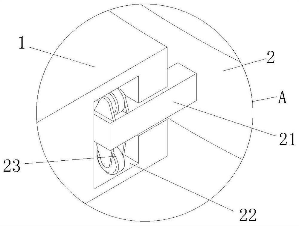
[0041] see Figure 2-3 , the second embodiment is to make a corresponding improvement on the basis of the first embodiment, and further fixedly connect several connecting sliders 21 on the outer surface of the crucible 2, and the number of connecting sliders 21 is determined according to the area of the outer ring of the crucible 2 There is no limitation on the quantity here, and at the same time, the inner wall of the protective shell 1 is provided with a limiting chute 22 with an inverted "T" shape in cross section, and the end of the connecting slide rod 21 facing away from the crucible 2 extends into the limiting chute 22 In the vertical groove, the connecting slide bar 21 is slidably connected with the limit chute 22, and the upper and lower sides surfaces of one end of the connecting slide bar 21 located in the limit chute 22 vertical grooves are all provided with limit wheels 23 that are slidably connected with the limit chute 22;
[0042] In this way, the limiting wh...
Embodiment 3
[0044] see Figure 1-6 , the third embodiment is to make corresponding improvements on the basis of the first and second embodiments, and further arrange a flow equalizing assembly 5 on the inner wall of the crucible 2, and the current equalizing assembly 5 includes several shunts with a ring-shaped structure Block 51, the diverter block 51 is inlaid on the inner wall of the crucible 2, and the number of the diverter blocks 51 is set according to the actual depth of the crucible 2, and there is no limit on the number here, and the side of the diverter block 51 facing away from the inner wall of the crucible 2 is opened There are grooves, and four mounting plates 52 arranged in a circular array and having a semi-circular structure are fixedly connected to the surface of the side of the diverter block 51 facing away from the crucible 2. The grooves coincide, and the groove of the shunt block 51 is fixedly connected to the inner wall of the side of the mounting plate 52 facing aw...
PUM
 Abstract
Description
Claims
Application Information
 - R&D
- Intellectual Property
- Life Sciences
- Materials
- Tech Scout
- Unparalleled Data Quality
- Higher Quality Content
- 60% Fewer Hallucinations
Browse by: Latest US Patents, China's latest patents, Technical Efficacy Thesaurus, Application Domain, Technology Topic, Popular Technical Reports.
© 2025 PatSnap. All rights reserved.Legal|Privacy policy|Modern Slavery Act Transparency Statement|Sitemap|About US| Contact US: help@patsnap.com


