Superfine fiber production equipment based on principle of composite spinning method

A technology for ultra-fine fibers and production equipment, which is applied in the directions of stretch spinning, filament generation, textiles and papermaking, and can solve the problems of time-consuming, labor-intensive and low-efficiency

Inactive Publication Date: 2021-09-21
崔晓珊
View PDF0 Cites 0 Cited by
  • Summary
  • Abstract
  • Description
  • Claims
  • Application Information

AI Technical Summary

Problems solved by technology

[0004] Generally, the staff manually apply the drug to the fiber, and then pull it manually, which is time-consuming and labor-intensive, and the efficiency is not high. Therefore, it is necessary to design an automatic drug application to the fiber, relying on the machine to pull the fiber, without excessive manual operation, saving Superfine fiber production equipment based on the principle of composite spinning method that saves time and labor and improves efficiency

Method used


Image

  • Superfine fiber production equipment based on principle of composite spinning method
  • Superfine fiber production equipment based on principle of composite spinning method
  • Superfine fiber production equipment based on principle of composite spinning method

Examples


Embodiment 1

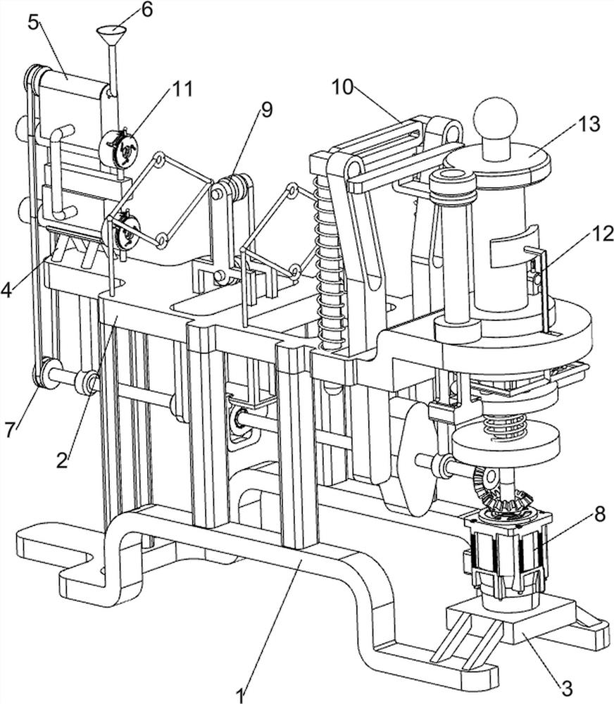
[0057] A kind of superfine fiber production equipment based on the principle of composite spinning method, such as figure 1 As shown, it includes a bottom frame 1, a placement plate 2, a motor support plate 3, a first fixed frame 4, a liquid passing frame 5, a lower liquid funnel 6, a blanking assembly 7, a winding assembly 8 and an extension assembly 9, and the bottom frame 1 The top is provided with a placement plate 2, and the rear side of the top of the placement plate 2 is provided with a first fixing frame 4. Two liquid passing frames 5 are connected to the first fixing frame 4. The liquid passing frames 5 are arranged up and down, and the upper side of the liquid passing frame 5 A lowering funnel 6 is provided on the front side of the top, and the bottom of the placement plate 2 is connected with a blanking assembly 7 for intermittent feeding of chemicals, and a stretching device for stretching the fibers is connected between the blanking assembly 7 and the placement pla...

Embodiment 2

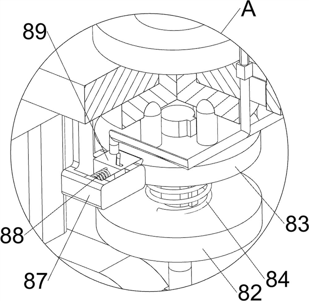
[0060] On the basis of Example 1, such as Figure 2 to Figure 6 As shown, the winding assembly 8 includes a servo motor 81, a first turntable 82, a chuck 83, a first spring 84, a rotating frame 85, a first sliding frame 86, a first limit frame 87, a second spring 88 and a wedge block 89, the top of the motor support plate 3 is provided with a servo motor 81, the output shaft of the servo motor 81 is connected with a first turntable 82, and the top of the first turntable 82 is slidably provided with a chuck 83, between the chuck 83 and the top of the first turntable 82 The first spring 84 is connected between them, the rotating frame 85 is placed on the front part of the placing plate 2, and the bottom of the rotating frame 85 cooperates with the chuck 83. The front side is symmetrically provided with a first spacer 87, and the first spacer 87 is slidably provided with a wedge 89. The left and right ends of the first slide 86 are slidably connected with the same side wedge 89. ...

Embodiment 3

[0065] On the basis of Example 2, such as Figure 7 and Figure 8 As shown, a lifting assembly 10 is also included, and the lifting assembly 10 includes a second cam 101, a second sliding frame 102, a second thread passing frame 103 and a third spring 104, and the front part of the rotating shaft 72 is provided with a second cam 101, placed The front part of the board 2 is slidingly provided with two second sliding frames 102. The second sliding frames 102 are arranged symmetrically on the left and right. The second sliding frames 102 are matched with the second cam 101. frame 103 , the second thread passing frame 103 is slidably connected to the upper part of the second sliding frame 102 , and two third springs 104 are connected between the second thread passing frame 103 and the top of the placing plate 2 .

[0066] The staff can pass the two fibers through the lower part of the liquid passing frame 5 on the same side, pass through the corresponding first thread passing fra...


PUM


Abstract

The invention relates to superfine fiber production equipment, in particular to superfine fiber production equipment based on the principle of a composite spinning method. Particularly, the superfine fiber production equipment based on the principle of a composite spinning method is capable of automatically feeding chemicals to fibers, pulling the fibers by a machine, avoiding excessive manual operation, saving time and labor and improving efficiency. The superfine fiber production equipment based on the principle of the composite spinning method comprises a bottom frame; a containing plate is arranged at the top of the bottom frame; a first fixed frame is arranged on the rear side of the top of the containing plate; and two liquid passing frames are connected between the two sides of the first fixed frame. By arranging a discharging assembly and a winding assembly, the work of chemical feeding and stretching is completed while fibers are driven to be pulled out forwards, so that manufacturing of superfine fibers is achieved; and by arranging a stretching assembly and a lifting assembly, the fibers are stretched, and manual pulling is not needed, so that the time and labor are saved.

Description

technical field [0001] The invention relates to an ultrafine fiber production equipment, in particular to an ultrafine fiber production equipment based on the principle of a composite spinning method. Background technique [0002] Fiber refers to a substance composed of continuous or discontinuous filaments. Fiber has a wide range of uses and can be woven into thin threads, thread ends and hemp ropes. It can also be woven into fiber layers when making paper or felt. It is also commonly used to make other materials. Or form a composite material together with other materials, that is, a composite fiber produced by composite spinning technology. The composite fiber becomes an ultrafine fiber after fiber opening. [0003] The production method of composite ultrafine fiber combines physical fiber opening method and chemical fiber opening method. After the fiber is drugged, it is pulled into ultrafine fiber. Combining the advantages of both makes the composite ultrafine fiber prod...

Claims


Application Information

Patent Timeline
Patent Type & Authority Applications(China)
IPC IPC(8): D01D5/16D01D11/06
CPCD01D5/16D01D11/06
Inventor 崔晓珊
Owner 崔晓珊
Why Eureka
Try Eureka