Cutter head with high rock breaking efficiency for tunnel boring machine

A technology of tunnel boring machine and rock breaking efficiency, applied in tunnels, mining equipment, earth-moving drilling, etc., can solve the problems of short service life, affecting the service life of the cutter head, overloading of the cutter, etc., and achieve the effect of reducing the cost of use

Active Publication Date: 2021-09-21
STATE GRID CORP OF CHINA +2
View PDF9 Cites 0 Cited by
  • Summary
  • Abstract
  • Description
  • Claims
  • Application Information

AI Technical Summary

Problems solved by technology

[0002] During the construction of tunnels in water conservancy projects, especially in the construction of diversion tunnels for pumped storage power stations, it is necessary to use tunnel boring machines for tunnel excavation. Tunnels; the diameter of the cutter head used by the tunnel boring machine is fixed at present. When the excavated tunnel corresponding to the diameter of the cutter head is excavated, it is difficult to use the cutter head to excavate tunnels with other diameters, resulting in The old cutter head was put on hold, and a suitable cutter head had to be remade, which increased the cost of the overall project; and the position of the existing cutter head was arranged by the technicians based on experience, but in the actual process of excavating the tunnel, The rock formation environment is complex, and it is easy to overload the cutter or eccentric wear between the cutter and the cutter, which in turn affects the service life of the overall cutterhead
Therefore, the existing tunnel boring machine cutter head has the problems of high cost of use and short service life in the process of use.

Method used


Image

  • Cutter head with high rock breaking efficiency for tunnel boring machine
  • Cutter head with high rock breaking efficiency for tunnel boring machine
  • Cutter head with high rock breaking efficiency for tunnel boring machine

Examples


Embodiment Construction

[0022] The present invention will be further described below in conjunction with the examples, but not as a basis for limiting the present invention.

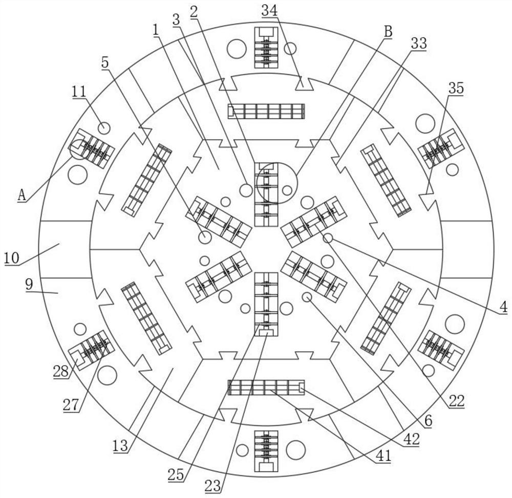
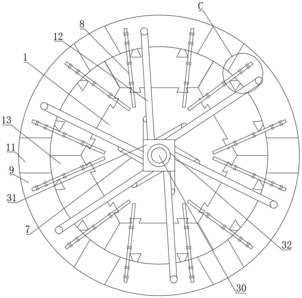
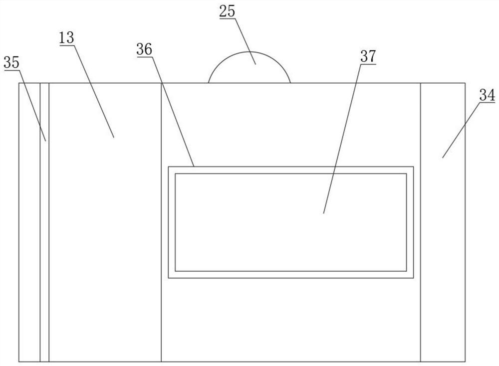
[0023] Example. A cutter head for a tunnel boring machine with high rock-breaking efficiency, which is composed of Figures 1 to 8As shown, the middle block 1 is included, and the upper surface of the middle block 1 is provided with a plurality of circular first hob installation grooves 2 evenly distributed; each first hob installation groove 2 is provided with a first hob assembly, each Both sides of the first hob installation groove 2 are respectively provided with a first installation groove 3 and a second installation groove 4; each first installation groove 3 is equipped with an electron beam generating device, each first installation groove 3 A focusing lens 5 is arranged at the notch; a first high-pressure water nozzle 6 is arranged in each second installation groove 4, and a first high-pressure water pipe 7 is connecte...


PUM


Abstract

The invention discloses a cutter head with high rock breaking efficiency for a tunnel boring machine. The cutter head comprises a middle block, wherein a plurality of first hob mounting grooves, first mounting grooves and second mounting grooves are formed in the middle block; a first hob assembly is arranged in each first hob mounting groove; an electron beam generating device and a focusing lens are mounted on each first mounting groove; a first high-pressure water nozzle and a first high-pressure water pipe are arranged in each second mounting groove; a plurality of telescopic rods are arranged on the lower surface of the middle block; a plurality of side blocks and filling blocks are arranged among all the telescopic rods; a second hob assembly, an electron beam generating device, a second high-pressure water nozzle and a second high-pressure water pipe are arranged on each side block; a connecting block is arranged between each side block and the middle block; and a third hob assembly is arranged on each connecting block. The cutter head disclosed by the invention can reduce the use cost and also has the advantages of long service life, high working efficiency, wide application range, convenience in maintenance, high use stability and high structural strength.

Description

technical field [0001] The invention relates to a cutterhead for a tunnel boring machine, in particular to a cutterhead for a tunnel boring machine with high rock breaking efficiency. Background technique [0002] During the construction of tunnels in water conservancy projects, especially in the construction of diversion tunnels for pumped storage power stations, it is necessary to use tunnel boring machines for tunnel excavation. Tunnels; the diameter of the cutter head used by the tunnel boring machine is fixed at present. When the excavated tunnel corresponding to the diameter of the cutter head is excavated, it is difficult to use the cutter head to excavate tunnels with other diameters, resulting in The old cutter head was put on hold, and a suitable cutter head needed to be remade, which increased the cost of the overall project; and the position of the existing cutter head was arranged by the technicians based on experience, but in the actual process of excavating th...

Claims


Application Information

Patent Timeline
Patent Type & Authority Applications(China)
IPC IPC(8): E21D9/10E21D9/11
CPCE21D9/1006E21D9/1066E21D9/1073E21D9/11Y02P70/10
Inventor 马明刚黄彦庆程剑林周智王桓徐文彬傅含富杜郑洁
Owner STATE GRID CORP OF CHINA
Why Eureka
Try Eureka