Fuel rail damper with locating features

A damper and fuel rail technology, applied in special fuel injection devices, low-pressure fuel injection, low-pressure fuel injection, etc., can solve problems such as loss, displacement, and increased noise of tail-end retainers

Pending Publication Date: 2021-09-21
ROBERT BOSCH GMBH
View PDF10 Cites 0 Cited by
  • Summary
  • Abstract
  • Description
  • Claims
  • Application Information

AI Technical Summary

Problems solved by technology

However, the spring and/or wire retainer may shift during assembly with the fuel rail
This is because the front end of the damper can be designed to be inserted into the open end of the fuel rail, but the rear end of the damper, which has a mirror image configuration, can experience interference with the open end of the fuel ra

Method used


Image

  • Fuel rail damper with locating features
  • Fuel rail damper with locating features
  • Fuel rail damper with locating features

Examples


Embodiment Construction

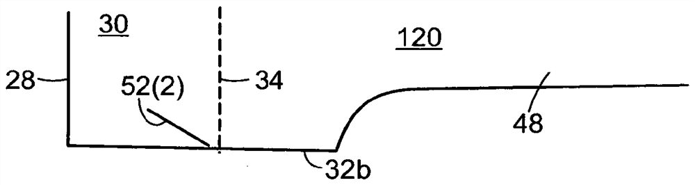
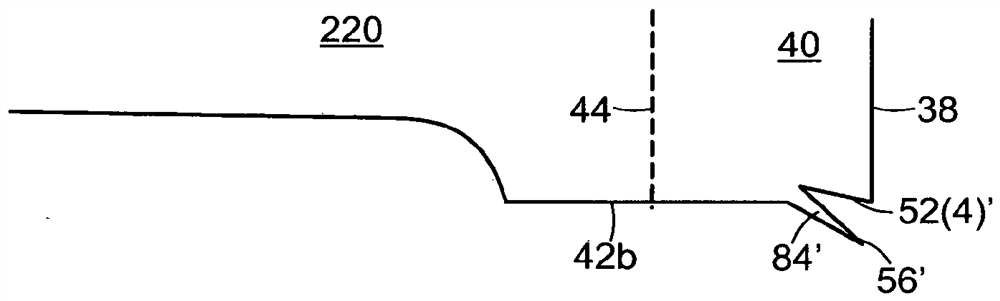
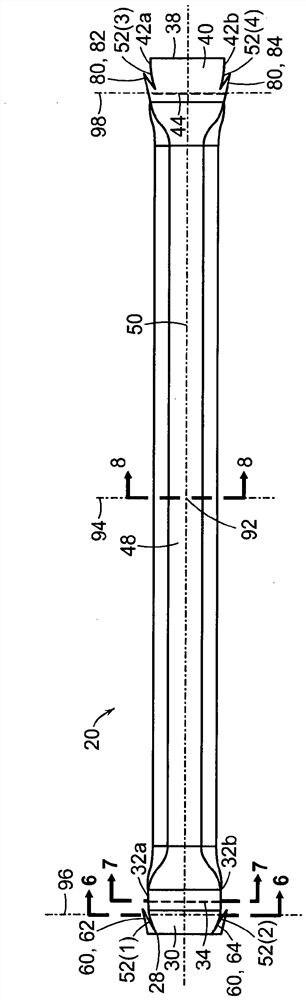
[0048] see figure 1 -3, the fuel system 1 is used to deliver fuel to the engine (not shown) of the vehicle. The fuel system 1 includes a fuel rail 2 , a damper 20 provided inside the fuel rail 2 , and a fuel injector 10 coupled to the fuel rail 2 . The fuel rail 2 is an elongated rectangular hollow tube comprising walls 4 defining fuel passages 6 . The fuel rail 2 includes fuel outlets 8 formed in a wall receiving the fuel injectors 10 . A fuel outlet 8 supplies fuel, such as gasoline or diesel, to the engine from a fuel passage 6 through a fuel injector 10 . Although three fuel outlets 8 and three fuel injectors 10 are illustrated, the fuel rail may include a greater or lesser number of fuel outlets 8 and fuel injectors 10 and the provided fuel outlets 8 and fuel injectors 10 The number corresponds to the number of fuel injectors and intake ports of the engine. The damper 20 is positioned and retained within the fuel rail 2 via retainers 60 , 80 provided on each end of t...


PUM


Abstract

A fuel injection system includes a fuel rail, and a damper that is disposed inside the fuel rail. The damper includes outwardly protruding first barbs formed integrally on one end of the damper and outwardly protruding second barbs formed integrally on an opposed end of the damper. The first barbs and the second barbs each engage the fuel rail inner surface, whereby the damper is located and retained within the fuel rail. The first barbs and the second barbs may be generally triangular in profile and each extend at an acute angle relative to the damper longitudinal axis. In addition, the first barbs and the second barbs are each oriented in the same direction relative to the longitudinal direction, whereby the damper is asymmetric when viewed in side view.

Description

Background technique [0001] A vehicle fuel rail is a conduit that supplies fuel to multiple fuel injectors. The fuel injectors inject fuel directly or indirectly into corresponding combustion chambers of the engine. Electromagnetic fuel injectors deliver fuel to the engine in metered pulses that are appropriately timed with the operation of the engine. In some cases, sequential energization of fuel injectors causes pressure pulsations within the fuel rail. Pressure pulsations can cause improper fuel distribution to the injectors and fuel line hammering, which causes vibration and audible noise. [0002] To reduce or eliminate pressure pulsations, dampers may be provided within the vehicle's fuel rail. In some systems, the damper is positioned and retained within the vehicle fuel rail via resilient retaining elements secured to the ends of the damper and suspending the damper within the fuel rail. In some arrangements, the resilient retaining element is a spring and / or wire...

Claims


Application Information

Patent Timeline
IPC IPC(8): F02M55/04F02M69/46
CPCF02M2200/315F02M55/04F02M69/465F02M37/0041F16F9/0436F16F15/02F02M2200/04
Inventor J·卡萨利A·E·古兹曼埃斯卡兰蒂J·查维兹
Owner ROBERT BOSCH GMBH
Why Eureka
Try Eureka