Microwave oscillator and matrix-type microwave oscillator based thereon

A technology of microwave oscillators and oscillators, applied in power oscillators, radio wave reflection/re-radiation, instruments, etc., can solve the problem that it is impossible to reach the acceptable value of equipment efficiency, limit the total power of microwave radiation, and it is difficult to achieve, etc. question

Pending Publication Date: 2021-09-21
马克·塔拉索夫
View PDF0 Cites 0 Cited by
  • Summary
  • Abstract
  • Description
  • Claims
  • Application Information

AI Technical Summary

Problems solved by technology

[0010] In the closest analog, even when only four magnetrons are arranged in a row and the microwave radiation frequencies of these magnetrons are close to each other, it is difficult to achieve a high degree of synchronization of the microwave radiation emitted by the magnetrons, and It is therefore difficult to achieve high device efficiency values, which clearly follows from Table 1 of RU2394357
However, the greater disadvantage of this analogue is that when several such linear oscillators of microwave radiation are arranged parallel to each other, that is, next to each other (but not one after the other), thus forming a two-dimensional It is practically impossible to achieve acceptable values ​​of equipment efficiency when the matrix
This fact limits the number of microwave sources that can be arranged over a small area and thus limits the total power of microwave radiation emitted by this known device for summing microwave radiation

Method used


Image

  • Microwave oscillator and matrix-type microwave oscillator based thereon
  • Microwave oscillator and matrix-type microwave oscillator based thereon
  • Microwave oscillator and matrix-type microwave oscillator based thereon

Examples


Embodiment Construction

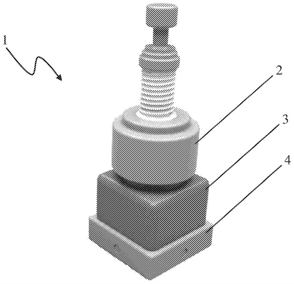
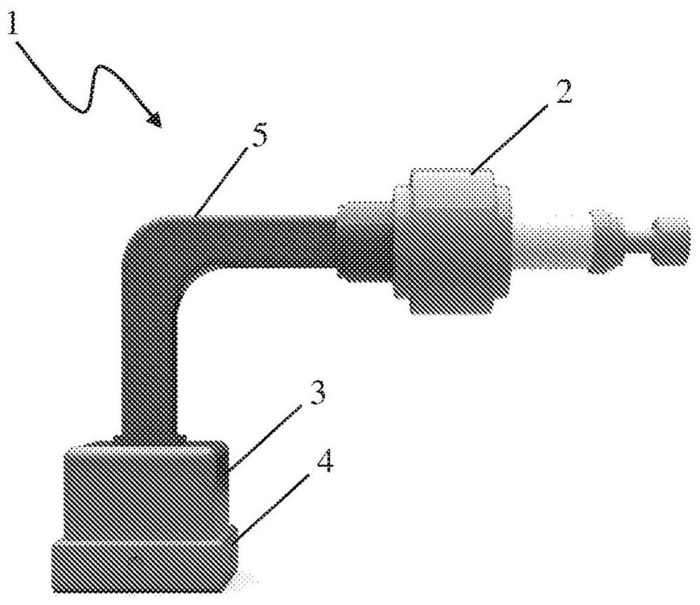
[0061] In general, a microwave oscillator 1 includes a microwave source 2 mounted on a cabinet 3 and a base 4 adjacent to the cabinet 3 . Source 2 can be mounted directly on enclosure 3 ( Figure 1a ), or installed through the waveguide 5 connecting the source 2 and the box 3 ( Figure 1b ).

[0062] The case 3 and the base 4 form the resonator of the oscillator 1 . The resonator can be made as a single part, or as a case 3 and a base 4 that are separate and electrically connected to each other.

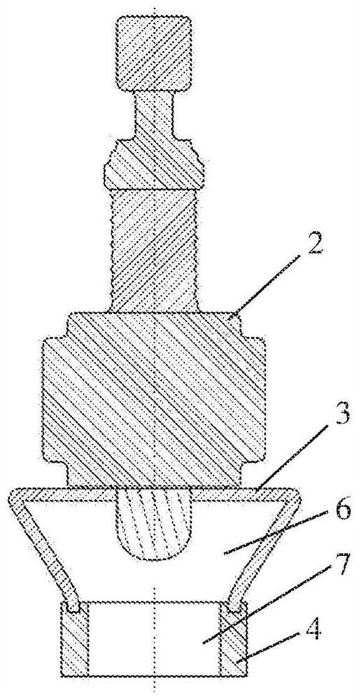
[0063] Figure 2a to Figure 2e A cross-sectional view of the internal arrangement of the disclosed oscillator 1 is shown.

[0064] A first channel 6 is formed in the housing 3 , via which microwave radiation emitted by the source 2 passes to the susceptor 4 . The casing 3 can be hollow, and then the first channel 6 can be the inner cavity of the casing 3 ( Figure 2a to Figure 2c ). Alternatively, the box body 3 can be block-shaped, i.e. solid ( Figure 2d ), then the first pa...


PUM


Abstract

The invention relates to the field of microwave emitting equipment, in particular to microwave oscillators. The proposed variants of an oscillator and a matrix-type microwave oscillator enable to efficiently direct microwave radiation from one or more microwave sources and sum up microwave radiations, thus ensuring high values of efficiency and output power, superior functional capabilities of the device, a high degree of synchronization of radiations emitted by said microwave sources. The microwave oscillator comprises a microwave source and a resonator with a microwave channel made therein. The resonator comprises a box and a base electrically connected to each other, while the microwave channel accommodates a suppressing means for suppressing a back wave. The matrix-type oscillator comprises a plurality of said microwave oscillators electrically connected to each other.

Description

technical field [0001] The invention relates to the field of microwave frequency equipment, in particular to a microwave radiation oscillator or a microwave oscillator. Background technique [0002] The high cost of sources of intense microwave radiation clearly hinders the development of future microwave technologies and their implementation on an industrial scale. At the same time, the production of medium-power microwave radiation sources, or microwave sources, such as magnetrons for consumer microwave ovens, is being developed globally, where the cost of the power unit is significantly lower than that of high-power microwave sources. Therefore, from the point of view of reducing the cost of equipment for generating cumulative intense microwave radiation, reducing the weight and size of equipment, and finding solutions for heat removal, the efficient search for microwave radiation emitted by multiple medium-power microwave sources and is a practical task. However, in or...

Claims


Application Information

Patent Timeline
IPC IPC(8): G01S13/88G01S7/03
CPCH03B1/04H03B9/10H05B6/701H05B2206/044H05B2206/043Y02B40/00
Inventor 马克·塔拉索夫
Owner 马克·塔拉索夫
Why Eureka
Try Eureka