Residual film bundling and recycling machine

A technology of recycling machine and residual film, applied in the field of agricultural machinery, can solve the problems of high labor intensity, high frequency of loading and unloading shutdown, and inability to bundle residual film, so as to improve work quality and efficiency, large tension and rotation space, and reduce soil entry. The effect of resistance

Active Publication Date: 2021-09-24
阿克苏市光大农机有限公司 +1
View PDF13 Cites 3 Cited by
  • Summary
  • Abstract
  • Description
  • Claims
  • Application Information

AI Technical Summary

Problems solved by technology

[0002] Plastic film mulching planting technology has been widely promoted and applied in Xinjiang due to its advantages of high-efficiency income increase, temperature increase and moisture conservation. However, the residual film after use has not been effectively recycled year after year, causing serious residual film pollution to farmland.
[0003] In order to solve the serious white pollution problem caused by the increase in the use of plastic film, more and more people have begun to develop and research residual film recycling machinery to solve the problems of low efficiency, high labor intensity and high cost of manual recycling.
[0004] The current residual film recycling machine is in use. After the residual film is recycled into the waste film box by the film winding roller, it is only collected in the box, and the residual film cannot be effectively bundled. It takes up a lot of space in the waste film box, and the loading and unloading stops frequently. High, resulting in low efficiency of film collection, and scattered on the ground when unloading, which brings inconvenience to subsequent work, so more and more people began to develop and research the method of bundling residual film

Method used


Image

  • Residual film bundling and recycling machine
  • Residual film bundling and recycling machine
  • Residual film bundling and recycling machine

Examples


Embodiment 1

[0075] With reference to the accompanying drawings, the structure of specific embodiments of the present invention is described in detail as follows:

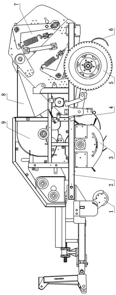
[0076] A residual film bundling recovery machine, comprising a main frame 2, a traveling wheel 5, a fan 9 arranged on the main frame 2, an air delivery channel 8, a depth-limiting roller 1, and a film holding tooth 6, and also includes a main frame 2 The segmented pick-up roller combination device and the residual film recycling automatic bundling device 7;

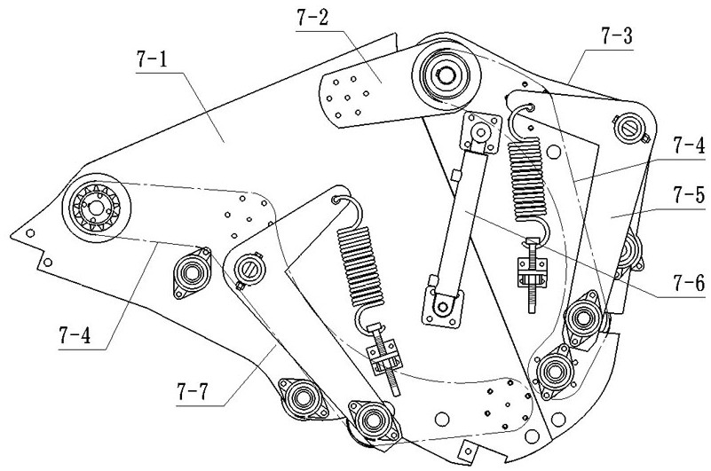
[0077] The automatic bundling device 7 for residual film recovery mainly includes two half-shells of the chassis that are fastened together, namely the half-shell of the chassis I7-1, the half-shell of the chassis II7-3, and the half-shell of the chassis I7- 1 is connected to the main frame, the upper part of the half-shell II7-3 of the chassis is hinged to the upper part of the half-shell I7-1 of the chassis, and there is a gap between the half-shell I7-1 and the half-she...

Embodiment 2

[0099] Compared with Embodiment 1, the present embodiment differs in that:

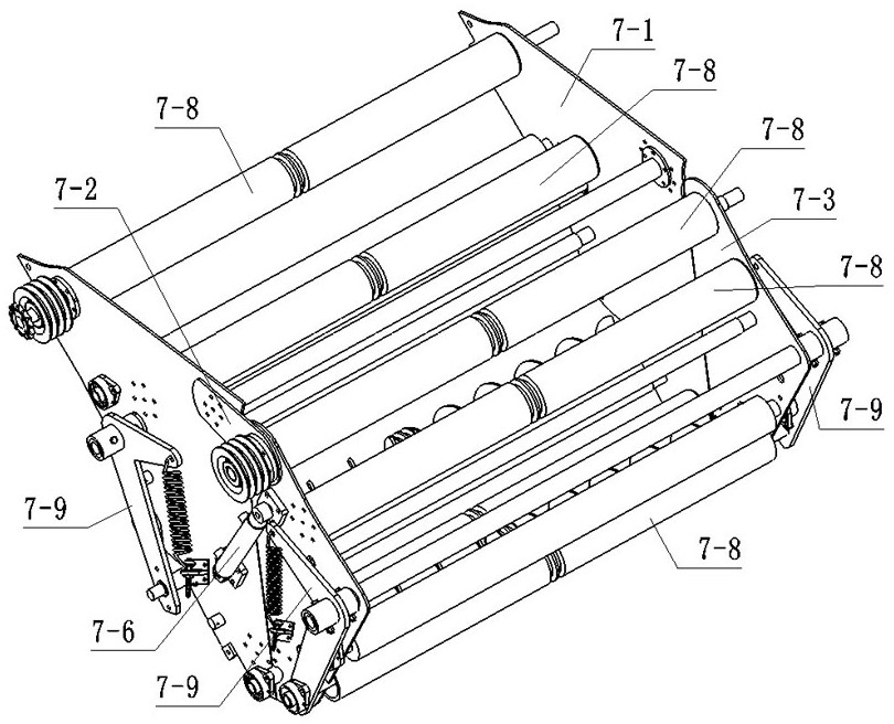
[0100] The guide bar 7-43 set on the lower surface of the belt body is one; the ring groove I7-81 set in the middle of the belt roller 7-8 is adapted to it, and one is provided correspondingly; The annular groove II7-117 provided on the pulley 7-114 is also adapted to it, and one is provided correspondingly.

[0101] Protruding upper guide bars 7-42 are respectively provided on both sides of the upper surface of the belt body of the endless wide belt 7-4. The cross-sectional shape of the upper guide bar 7-42 is a trapezoid with a wide top and a narrow bottom, and the cross-sectional shape of the guide bar 7-43 is a trapezoid with a wide top and a narrow bottom.

[0102] The cross-sectional shape of the bump 7-41 is square, such as a rectangle or a square, and the height of the bump 7-41 from the surface of the belt body is 0.5 mm.

Embodiment 3

[0104] Compared with Embodiment 1, the present embodiment differs in that:

[0105] The connection between the upper section arm 7-132 and the lower section arm 7-134 of each group of ">" type crank arms 7-131 is at an angle of 30 degrees, and the pressure spring is a compression spring 7-19. The pressing arm 7-13 is connected to the fastening and pressing device II provided on the half-shell of the chassis, and the structure of the fastening and pressing device II includes a support plate 7-21, a screw rod II 7-20, and the support plate 7-21 is provided with a perforation, and the screw rod II 7-20 passes through the perforation to connect with the press arm 7-13, and the other end is sequentially covered with a compression spring 7-19 and a compression nut 7-18, The compression nut 7-18 is threadedly connected with the screw mandrel II 7-20 and supported on the compression spring 7-19 inside. like Figure 17 As shown in the figure, the structure of the pressurizing arm 7-1...


PUM


Abstract

The invention relates to the technical field of agricultural machinery, in particular to a residual film bundling and recycling machine which comprises a main machine frame, walking wheels, a draught fan arranged on the main machine frame, an air conveying channel, a depth limiting roller and film raking teeth and further comprises a sectional type picking-up roller combined device and a residual film recycling and automatic bundling device which are arranged on the main machine frame. The plastic film residue recycling and automatic bundling device comprises two case half shells which are buckled together, and a belt pressurizing and impurity removing combined device is arranged in each case half shell. The sectional type pick-up roller combined device mainly comprises a sectional type pick-up roller and a film connecting tooth device. The residual film bundling and recycling machine is simple in structure, economical and practical, and when the residual film is recycled and bundled, the sectional type picking roller combined device is utilized, so that the soil penetrating resistance of elastic teeth is greatly reduced, and the film recycling and demolding operation efficiency can be effectively improved; and by means of the plastic film residue recycling and automatic bundling device, the working quality and efficiency of bundling operation of the whole residual film recycling machine are greatly improved.

Description

technical field [0001] The invention relates to the technical field of agricultural machinery, in particular to a residual film bundling recovery machine. Background technique [0002] Plastic film mulching planting technology has been widely promoted and applied in Xinjiang because of its advantages of high efficiency in increasing income, increasing temperature and preserving moisture. However, the residual film after use cannot be effectively recycled year after year, causing serious residual film pollution to farmland. [0003] In order to solve the serious white pollution problem caused by the increase in the use of plastic film, more and more people have begun to develop and research residual film recycling machinery to solve the problems of low efficiency, high labor intensity and high cost of manual recycling. [0004] The current residual film recycling machine is in use. After the residual film is recycled into the waste film box by the film winding roller, it is o...

Claims


Application Information

Patent Timeline
Patent Type & Authority Applications(China)
IPC IPC(8): B29B17/00B29B17/02A01B43/00
CPCB29B17/0026B29B17/02A01B43/00Y02W30/62
Inventor 王速王鲁
Owner 阿克苏市光大农机有限公司
Why Eureka
Try Eureka