
Underground oil-water separation same-well injection-production system and pipe column

A technology of oil-water separation, injection and production in the same well, applied in wellbore/well components, production fluids, earth-moving drilling and production, etc., can solve the problems of increased water content of produced fluid, increased cost of gathering, transportation and sewage treatment, lifting, etc. , to achieve the effect of high lifting head and lower comprehensive development cost

Active Publication Date: 2021-09-24
PETROCHINA CO LTD
View PDF5 Cites 4 Cited by
  • Summary
  • Abstract
  • Description
  • Claims
  • Application Information

AI Technical Summary

Problems solved by technology

[0003] The purpose of the present invention is to provide a downhole oil-water separation and injection-production system in the same well and a pipe string to solve the problem in the prior art that the water content of the production fluid is continuously increasing, which leads to an increase in the cost of lifting, gathering and transportation, and sewage treatment

Method used


Image

  • Underground oil-water separation same-well injection-production system and pipe column
  • Underground oil-water separation same-well injection-production system and pipe column
  • Underground oil-water separation same-well injection-production system and pipe column

Examples


Embodiment 1

[0078] Embodiment one (adopt above note)

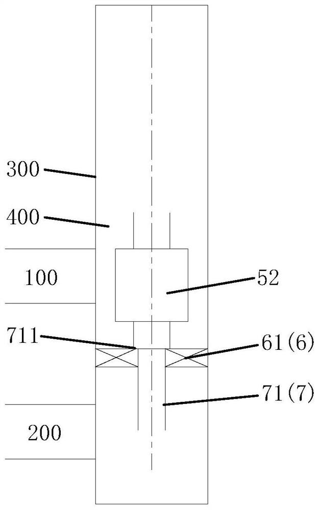
[0079] Such asfigure 1 , figure 2 , image 3 , Figure 4 As shown, in Embodiment 1, the production layer 100 is located above the water injection layer 200, and the isolation system 6 includes a first packer 61 arranged in the downhole casing 300 and located between the production layer 100 and the water injection layer 200. A packer 61 separates the production layer 100 from the water injection layer 200 to prevent the production layer 100 from colluding with the water injection layer 200. The oil jacket annulus 400 is located above the first packer 61, and the production layer 100 communicates with oil and water through the oil jacket annulus 400. The inlet 21 is connected, and the oil-water mixture in the production layer 100 flows through the oil jacket annulus 400 and the oil-water inlet 21 to enter the oil-water separation system 2; A seal is inserted between the sealing tube 71 and the first packer 61, and the upper end o...

Embodiment 2

[0083] Embodiment two (take note on)

[0084] Such as Figure 5 , Figure 6 As shown, in the second embodiment, the production layer 100 includes the first production layer 110, the water injection layer 200 includes the first water injection layer 210 above the first production layer 110, and the isolation system 6 includes the first production layer 110 and the second production layer. The second packer 62 between the first water injection layer 210 and the third packer 63 between the first water injection layer 210 and the oil jacket annulus 400; the second packer 62 and the third packer 63 Connected with the diversion system 7, there is a water injection annulus 500 between the diversion system 7 and the downhole casing 300, the water injection annulus 500 is located between the second packer 62 and the third packer 63 and is connected to the first water injection layer 210, the diversion system 7 has a water flow channel connecting the reinjection system 3 with the wa...

Embodiment 3

[0100] Embodiment three (take two ends and note the middle)

[0101] Such as Figure 11 As shown, in the third embodiment, the production layer 100 includes the first production layer 110 and the second production layer 120, the water injection layer 200 includes the first water injection layer 210, the first water injection layer 210 is located above the first production layer 110, the second Below the production layer 120, the downhole oil-water separation injection-production system in the third embodiment includes all the technical features of the second embodiment, and also includes the following technical features: the third packer 63 is located below the second production layer 120, and the second production The oil-water mixture in the layer 120 flows through the oil jacket annulus 400 and the oil-water inlet 21 into the oil-water separation system 2 in sequence.


PUM


Abstract

The underground oil-water separation same-well injection-production system and a pipe column. The underground oil-water separation same-well injection-production system comprises a lifting system, an oil-water separation system and a reinjection system which are sequentially connected from top to bottom, wherein the oil-water separation system is provided with an oil-water inlet communicating with a production layer, an oil outlet communicating with the lifting system and a water outlet communicating with the reinjection system, the reinjection system communicates with a water injection layer, an oil-water mixture of the production layer enters the oil-water separation system through the oil-water inlet, the oil-water separation system divides the oil-water mixture into separated rich oil and separated water, the separated rich oil flows out of the oil outlet and then is extracted through the lifting system, and the separated water flows out of the water outlet and then is reinjected into the water injection layer through the reinjection system. According to the underground oil-water separation same-well injection-production system, oil-water separation, water injection and oil extraction can be achieved in one well at the same time, and the device can be tripped into special structure wells such as an inclined well, a highly-deviated well and a directional well and can be used for 51 / 2''cased wells.

Description

technical field [0001] The invention relates to the technical field of oil field recovery, in particular to a downhole oil-water separation and injection-production system in the same well and a pipe string. Background technique [0002] At present, many oilfields have entered the period of high water-cut production. The water content of some oil fields has exceeded 90%, and the water content of some blocks has even exceeded 95%. Due to the increasing water content of the produced fluid, the cost of lifting, gathering and transportation and sewage treatment has increased. The efficiency of oil field development has declined, and many oil wells have been forced to shut down and stop production. In addition, a large amount of sewage treatment has also brought potential environmental protection hazards. Contents of the invention [0003] The purpose of the present invention is to provide a downhole oil-water separation and injection-production system in the same well and a pi...

Claims


Application Information

Patent Timeline
Patent Type & Authority Applications(China)
IPC IPC(8): E21B43/00E21B43/38E21B43/40E21B43/20E21B43/14F04D13/10F04C13/00
CPCE21B43/128E21B43/385E21B43/20E21B43/14F04D13/10F04C13/008Y02E10/10
Inventor 高扬刘合俞佳庆李益良郑立臣童征师国臣韩岐清郑国兴
Owner PETROCHINA CO LTD
Learn More