Oil well intelligent calibration self-inspection method and device

A self-inspection device and oil well technology, applied in earthwork drilling, wellbore/well components, production fluids, etc., can solve problems such as downhole flow, water cut measurement accuracy reduction, parameter drift, control failure, etc., to improve crude oil recovery efficiency, improve accuracy, and achieve production optimization

Active Publication Date: 2019-09-17
XIAN SITAN INSTR
View PDF8 Cites 2 Cited by
  • Summary
  • Abstract
  • Description
  • Claims
  • Application Information

AI Technical Summary

Problems solved by technology

[0004] A reasonable working system and production stimulation measures are based on the accuracy of data. With long-term work, the measurement channel of the downhole distribution device is affected by crude oil scaling, gas content of downhole production fluid, sediment, etc., resulting in measurement accuracy of downhole flow and water cut. Gradually decreases
At the same time, in the high temperature and high pressure environment, the electronic components of the downhole distribution device are gradually aging, and the parameters drift, which affects the accuracy of the measurement; the oil nozzle of the downhole distribution device is fouled, and the motor is worn out, causing the risk of control failure

Method used


Image

  • Oil well intelligent calibration self-inspection method and device
  • Oil well intelligent calibration self-inspection method and device
  • Oil well intelligent calibration self-inspection method and device

Examples


Embodiment 1

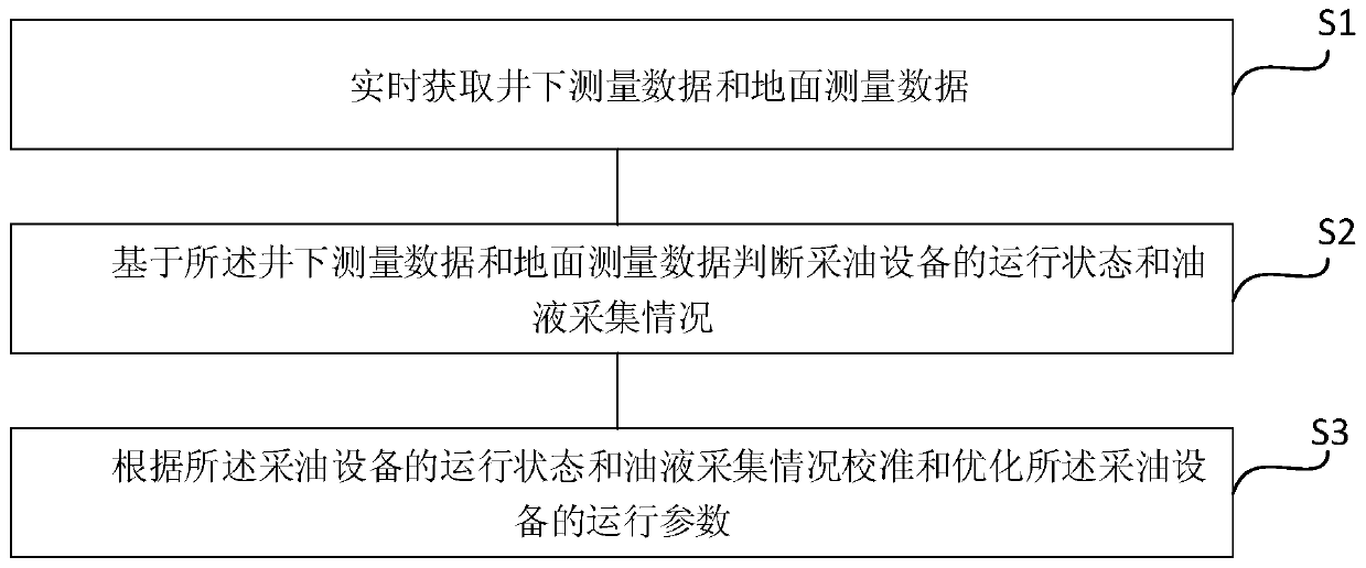
[0046] See figure 1 , figure 1 It is a flow chart of an oil well intelligent calibration self-inspection method provided by an embodiment of the present invention. The oil well intelligent calibration self-inspection method of this embodiment includes:

[0047] S1: Obtain downhole measurement data and surface measurement data in real time;

[0048] Specifically, the relevant parameters of each oil layer are collected in real time through the distribution device located in each oil layer downhole, wherein the relevant parameters of each oil layer include but are not limited to the flow rate, water content, temperature, pressure, and nozzle opening of the collected oil. , the internal pressure and external pressure of the oil pipeline, the cable head voltage, motor voltage, working current and working temperature of each oil reservoir distribution device, the power supply voltage of the instrument, and the electrical parameters of key components; the collected oil is obtained ...

Embodiment 2

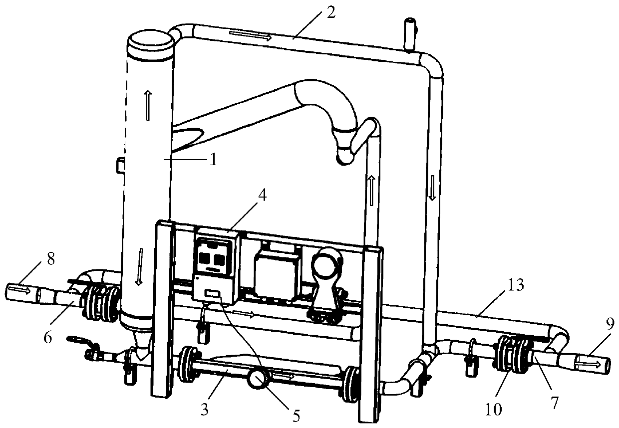
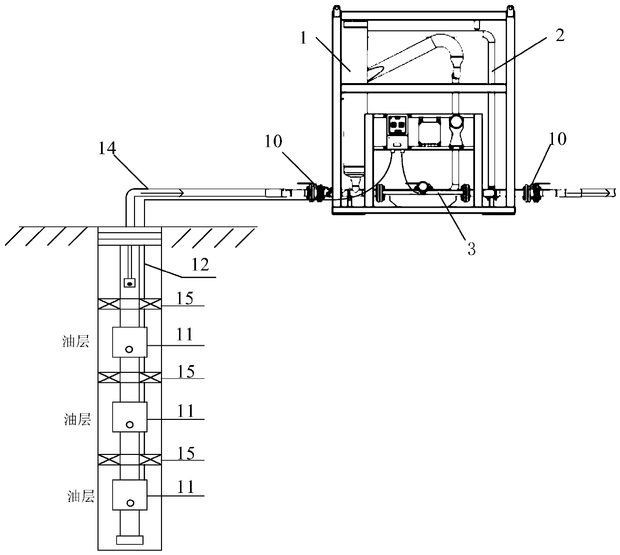
[0062] On the basis of the above embodiments, this embodiment provides an oil well intelligent calibration self-checking device. The oil well intelligent calibration device has the functions of data acquisition and analysis, self-calibration, self-test and life cycle management. The oil well intelligent calibration self-inspection device includes a ground measurement unit and a ground control unit, wherein the ground measurement unit is used to obtain the production and water content of the collected oil, and the ground control unit is connected to a plurality of downhole distribution devices and the ground measurement unit respectively. The unit is used to obtain the measurement values ​​of the plurality of downhole distributors and the mass flow meter, and perform self-inspection and parameter optimization according to the measurement values.

[0063] Specifically, see figure 2 and image 3 , figure 2 It is a structural schematic diagram of an oil well intelligent calib...


PUM


Abstract

The invention discloses an oil well intelligent calibration self-inspection method and device. The method comprises the steps that downhole measuring data and ground measuring data are acquired in real time; the operation state of oil extraction equipment and oil liquid collecting situation are judged based on the downhole measuring data and the ground measuring data; and the operation parameters of the oil extraction equipment are calibrated and optimized according to the operation state of oil extraction equipment and oil liquid collecting situation. According to the oil well intelligent calibration self-inspection method, big data analysis, modeling and intelligent optimization decision can be conducted based on information of liquid generating in all layers downhole and ground metrical information collected in real time, reasonable oil extraction work system is established, stabilizing oil production and controlling water cut are achieved, producible oil index is improved, and production optimization is achieved.

Description

technical field [0001] The invention belongs to the technical field of oil and gas detection, and in particular relates to an oil well intelligent calibration self-inspection method and device. Background technique [0002] At present, oil well production in oil fields has gradually changed from traditional general extraction to multi-layer fine extraction. As the oilfield enters the later stage of development, high water-bearing layers and medium-low water-bearing layers are alternately arranged, and the main production layers of many oil wells also have high water cuts, making some low water cut and low permeability oil layers unable to be normally exploited. [0003] In order to solve these problems, the intelligent layered oil recovery technology is proposed, that is, a production distribution device is installed in each oil production layer, and the layers are separated by cable packers, connected to the ground through cables, and the flow rate, Production fluid inform...

Claims


Application Information

Patent Timeline
Patent Type & Authority Applications(China)
IPC IPC(8): E21B47/00E21B47/06E21B47/07E21B47/12E21B43/12
CPCE21B47/00E21B47/06E21B47/12E21B43/12E21B47/07Y02P90/02
Inventor 牛云鹏孙晓飞王磊李金华
Owner XIAN SITAN INSTR
Why Eureka
Try Eureka