Connecting piece and assembling process of cardiovascular implant and conveying equipment

A technology for conveying equipment and connectors, applied in the field of implantation of cardiovascular implants, can solve the problems of increasing the surface area of ​​foreign body content, uneven stress of the implant, deviation and twist of the implant, etc., so as to reduce the risk of falling off, Reduced risk of microthrombi, reduced solder joint effectiveness

Pending Publication Date: 2021-09-28
GUANGDONG PULSE MEDICAL SCI & TECH CO LTD
View PDF6 Cites 0 Cited by
  • Summary
  • Abstract
  • Description
  • Claims
  • Application Information

AI Technical Summary

Problems solved by technology

[0004] (1) Since the tubular cardiovascular implant 2' and the silk braided cardiovascular implant 3' need to connect the threaded structure 1' at the connection end 21', the height of the raised part will inevitably be increased, thereby increasing the High risk of developing microthrombosis
[0005] (2) All the braided wires of the braided cardiovascular implant 3' penetrate into the tubular structure, which will cause the braided wires to be partially staggered and stacked, resulting in uneven stress on each part of the implant, which is easy to receive during the operation. When the sheath and the implant are released from the sheath, the implant is deflected and twisted, affecting the normal release and recovery and even endangering the life of the patient
[0006] (3) Whether it is a tubular cardiovascular implant 2' or a silk braided cardiovascular implant 3', due to the need for an additional thread structure, especially the silk braided cardiovascular implant 3' also requires a welded closure structure 31', there are many solder joints, which increases the risk of falling off. In addition, it also increases the content of foreign matter in the body and the overall surface area, thereby increasing the risk of corrosion

Method used


Image

  • Connecting piece and assembling process of cardiovascular implant and conveying equipment
  • Connecting piece and assembling process of cardiovascular implant and conveying equipment
  • Connecting piece and assembling process of cardiovascular implant and conveying equipment

Examples


Embodiment 1

[0055] see Figure 5 As shown, the embodiment of the present application provides a connector 1 for connecting a cardiovascular implant and a delivery device. The connector 1 includes a main body 11, the main body 11 is formed with a connecting hole 111 and a threaded hole 112, the connecting hole 111 is used for inserting the mounting part of the cardiovascular implant, and the threaded hole 112 is used for threaded connection with the delivery device.

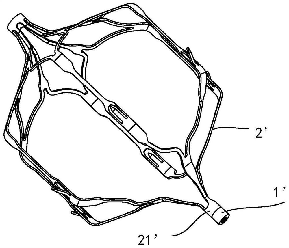
[0056] like Image 6 As shown, when using the connecting piece 1 to connect the tube-like cardiovascular implant 2 and the delivery device, one end of the tube is laser cut into several mounting feet (that is, a short columnar structure, of course, it is not limited to this, and it can also be Set according to actual needs), and then insert each mounting foot evenly into the corresponding connection hole 111 of the connector 1, and then use injection welding to connect each mounting foot to the connector 1, and then use the ...

Embodiment 2

[0067] The connector 1 in this embodiment is an improvement on the basis of Embodiment 1. The technical content disclosed in Embodiment 1 will not be described repeatedly, and the content disclosed in Embodiment 1 also belongs to the content disclosed in this embodiment.

[0068] Specifically, such as Figure 10 As shown, the different structures disclosed in Embodiment 2 and Embodiment 1 are as follows:

[0069] There are multiple connecting holes 111 , and the multiple connecting holes 111 plus the threaded holes 112 are arranged in a square array with the threaded holes 112 as the center. Here, for example, there are eight connecting holes 111 , one threaded hole 112 is located in the center, and nine connecting holes 111 and threaded holes 112 are arranged in a square array.

Embodiment 3

[0071] The connector 1 in this embodiment is an improvement on the basis of Embodiment 1. The technical content disclosed in Embodiment 1 will not be described repeatedly, and the content disclosed in Embodiment 1 also belongs to the content disclosed in this embodiment.

[0072] Specifically, such as Figure 11 As shown, the different structures disclosed in Embodiment 3 and Embodiment 1 are as follows:

[0073] The number of connecting holes 111 is multiple, and the multiple connecting holes 111 are arranged in a circular array around the threaded hole 112;

[0074] The number of array rings formed is multiple (that is, a plurality of ring structures centered on the threaded hole 112 and having unequal radii, and any ring structure is formed by a plurality of connecting holes 111 at intervals in sequence), and The connection holes 111 in any two adjacent array rings are arranged alternately. Here, for example, one threaded hole 112 is located at the center, the number of c...


PUM


Abstract

The invention relates to the technical field of cardiovascular implant implantation, in particular to a connecting piece and an assembling process of a cardiovascular implant and conveying equipment, the connecting piece is used for connecting the cardiovascular implant and the conveying equipment, the connecting piece comprises a main body, a connecting hole and a threaded hole are formed in the main body, the connecting hole is used for inserting a mounting part of the cardiovascular implant, and the threaded hole is used for being in threaded connection with the conveying equipment. When the connecting piece is used for connecting the cardiovascular implant and the conveying equipment, a connecting end or a closing-up structure is reduced, the risk of generating micro thrombus can be effectively reduced, stress on each part of the implant is uniform, the structure is simple, welding spots are reduced, in addition, the foreign matter content and the surface area are also reduced, and the risk of corrosion is further reduced.

Description

technical field [0001] The present application relates to the technical field of cardiovascular implant implantation, and in particular to a connector, a cardiovascular implant and an assembly process of a delivery device. Background technique [0002] Currently, if figure 1 As mentioned above, the common cardiovascular implants on the market mostly use metal tubes to be formed by laser cutting and then heat treatment, or as Figure 2 to Figure 4 As shown, metal wire is used for weaving and then heat treatment for molding. However, many cardiovascular implants are connected to delivery devices by threads, so tubular cardiovascular implants usually need to be additionally connected with a threaded structure 1 ′ at the connection end 21 ′, while silk braided cardiovascular implants Not only the threaded structure 1' is required to be installed at the connection end 21', but also the braided wire needs to be closed to form a closed-loop structure. At present, it is mainly rea...

Claims


Application Information

Patent Timeline
IPC IPC(8): A61F2/82A61F2/90A61F2/91A61F2/95
CPCA61F2/82A61F2/90A61F2/91A61F2/95A61F2220/0025A61F2240/002
Inventor 阮成民沈斌粱玉麟马为李运高邓嘉铭郭俊乐
Owner GUANGDONG PULSE MEDICAL SCI & TECH CO LTD
Why Eureka
Try Eureka