Anti-deformation punching device for stainless steel pipes

A stainless steel tube, anti-deformation technology, applied in the field of punching devices, can solve the problems of reducing work efficiency, cumbersome, stainless steel tube deformation, etc., and achieve the effects of improving work safety, reducing labor intensity, and improving work efficiency

Active Publication Date: 2021-09-28
南通久鼎特种钢管有限公司
View PDF8 Cites 0 Cited by
  • Summary
  • Abstract
  • Description
  • Claims
  • Application Information

AI Technical Summary

Problems solved by technology

However, when the existing punching device is used in operation, the operator generally handles the stainless steel pipe to process. This method is not only unsafe, but also securely fixes the stainless steel pipe, and the stainless steel pipe will be deflected during punching. shift, resulting in a lower pass rate of the finished product, and the punching part cannot be protected, which will cause the stainless steel tube to be deformed at the moment of punching. At the same time, the stainless steel tube needs to be placed in the On the punching device, and after the operation is completed, the stainless steel pipe must be removed. This operation process is not only cumbersome, but also increases the labor intensity of the staff and greatly reduces the work efficiency.

Method used


Image

  • Anti-deformation punching device for stainless steel pipes
  • Anti-deformation punching device for stainless steel pipes
  • Anti-deformation punching device for stainless steel pipes

Examples


Embodiment 1

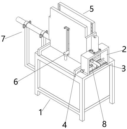
[0033] Such as Figure 7As shown, in this embodiment, in order to facilitate the placement of the steel pipe body 8 in the discharge mechanism 5, the limit plates 35 are respectively fixedly installed on the side walls of the two sides of the second material guide plate 28, and the limit plates 35 are located in the movable position. Between the blocks 29, the first sliding block 36 is fixedly installed on the side walls of both sides of the limiting plate 35, the first sliding block 36 passes through the bar-shaped through groove 31, and the first sliding block 36 is movably installed in the second sliding groove 32, the side wall of the limit plate 35 is provided with a through spring groove 37, and a retaining ring 39 is fixedly installed in the two ends of the spring groove 37, and a second compression spring 38 is fixedly installed in the groove of the spring groove 37. The two ends of the two compression springs 38 are fixedly installed with a limit clamp 40, and the lim...

Embodiment 2

[0035] like Figure 6 As shown, in this embodiment, in order to realize the automatic discharging operation of the steel pipe body 8, the discharging frame 24 is fixedly installed on the first material guide plate 20, and the discharging frame 24 is located between the support rods 23, and the discharging frame Both sides of the inner wall of 24 are provided with a group of symmetrical grooves 25 respectively, and fixed rod 26 is fixedly installed in the groove of groove 25, and first compression spring 27 is set on the body of fixed rod 26, and the top surface of first compression spring 27 Fixedly installed on the top surface in the groove of the groove 25, the outer wall both sides of the discharge frame 24 are respectively provided with a strip-shaped through-slot 31, and the strip-shaped through-slot 31 is located between the grooves 25, and the strip-shaped through-slot 31 Both sides of the groove wall are respectively provided with a second sliding groove 32, and a grou...

Embodiment 3

[0037] like Figure 8 As shown, in this embodiment, in order to push the steel pipe body 8 onto the clamping mechanism 3 in a fully automatic manner, the rear end of the punching machine body 1 is fixedly equipped with a support cross bar 42, and the top surface of the support cross bar 42 A symmetrical support vertical bar 43 is fixedly installed, and two groups of symmetrical mounting blocks 44 present a semi-circular shape. There is a side block 45, the top surface of the side block 45 is provided with a through hole 46, the bolt 47 passes through the upper and lower symmetrical side block 45 and extends to the outside, the nut 48 is threaded with the bolt 47, and the electric push rod 49 is located on the mounting block 44, and the front end of the electric push rod 49 is fixedly equipped with a push piece 50, the bottom surface of the push piece 50 is fixedly installed with a second sliding block 51, and the second sliding block 51 is movably installed in the first slidin...


PUM


Abstract

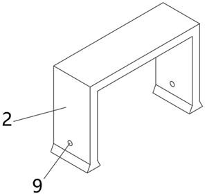
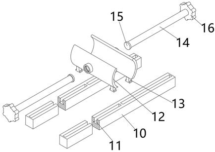
The invention discloses an anti-deformation punching device for stainless steel pipes. The anti-deformation punching device comprises a punching machine body and an inverted concave plate, wherein the inverted concave plate is located at the front end portion of the top face of the punching machine body; a clamping and fixing mechanism is arranged below the inverted concave plate, and the clamping and fixing mechanism comprises battens, a clamping plate and threaded rods; and a material guiding mechanism is arranged on the bottom face of the punching machine body, the material guiding mechanism comprises a first material guiding plate and supporting rods, and a discharging mechanism is arranged on the material guiding mechanism. The invention relates to the anti-deformation punching device for the stainless steel pipes, and belongs to the field of punching devices. The stainless steel pipes are sequentially pushed to the clamping and fixing mechanism by an automatic working mode instead of a manual operation mode through cooperative use of the material guiding mechanism, the discharging mechanism and a material pushing mechanism, then the stainless steel pipes are manually fixed through the clamping and fixing mechanism, and stamping operation is achieved, so that the labor intensity of workers is reduced, and the working efficiency is greatly improved.

Description

technical field [0001] The invention relates to the field of punching devices, in particular to an anti-deformation punching device for stainless steel pipes. Background technique [0002] Stainless steel pipe is a hollow long round steel, mainly widely used in petroleum, chemical, medical, food, light industry, mechanical instrumentation and other industrial pipelines and mechanical structural components. In addition, when the bending and torsional strength are the same, the weight is lighter, so it is also widely used in the manufacture of mechanical parts and engineering structures. It is also commonly used as furniture and kitchen utensils. When the existing stainless steel pipes are produced and processed, punching devices, that is, punching equipment, are usually used to perform punching operations on the stainless steel pipes, so as to process and shape the stainless steel pipes. However, when the existing punching device is used in operation, the operator generally...

Claims


Application Information

Patent Timeline
Patent Type & Authority Applications(China)
IPC IPC(8): B21D28/02B21D28/04B21D43/00B21D43/20
CPCB21D28/02B21D28/04B21D43/006B21D43/20
Inventor 唐红艳
Owner 南通久鼎特种钢管有限公司
Why Eureka
Try Eureka