
Shaped electric box protective shed with self-locking function and mounting method

A protective shed and stereotyped technology, applied in the field of stereotyped electric box protective shed and installation, can solve the problems of low turnover efficiency, large space occupation, low installation and disassembly efficiency, etc., and achieve convenient installation and disassembly, firm fixation, and simple installation Effect

Active Publication Date: 2021-09-28
THE FOURTH OF CHINA EIGHTH ENG BUREAU
View PDF5 Cites 1 Cited by
  • Summary
  • Abstract
  • Description
  • Claims
  • Application Information

AI Technical Summary

Problems solved by technology

[0002] Common electrical box protective sheds on the construction site are mostly made of welded steel square tubes. The electrical box protective sheds made by welding have a low degree of finalization, low installation and disassembly efficiency, and low turnover efficiency. Moreover, the protective sheds are large in size and light in weight. It takes up a lot of space and it is easy to cause deformation and damage in extreme cases, which is not convenient for turnover and allocation; and the fixing method of the ordinary electric box protective shed and the ground generally uses expansion screws, which has poor fixing effect and low turnover efficiency

Method used


Image

  • Shaped electric box protective shed with self-locking function and mounting method
  • Shaped electric box protective shed with self-locking function and mounting method
  • Shaped electric box protective shed with self-locking function and mounting method

Examples


Embodiment Construction

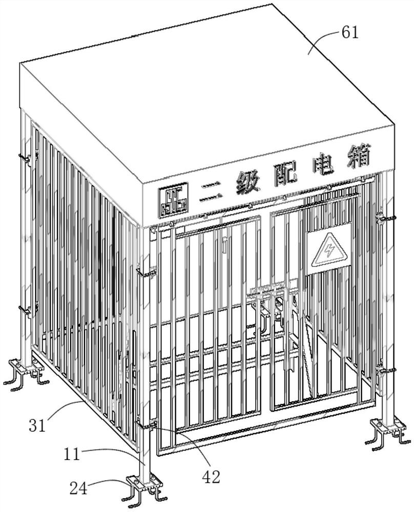
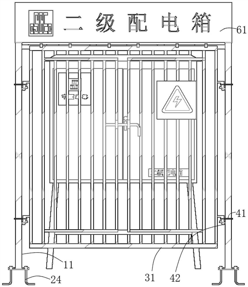
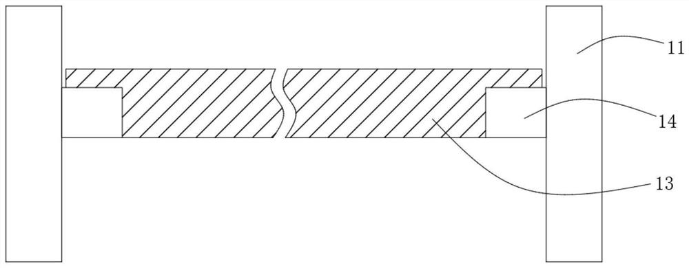
[0028] The following will clearly and completely describe the technical solutions in the embodiments of the present invention with reference to the accompanying drawings in the embodiments of the present invention. Obviously, the described embodiments are only some, not all, embodiments of the present invention.

[0029] refer to Figure 1-11 , a self-locking function of the stereotyped electric box protective shed, including protective shed column 11, horizontal column 13, plug-in fixed embedded parts, grid-type protective sheet 31, self-locking connector, steel mesh anti-smashing layer, Rainproof layer 61;

[0030] And through the following connections to achieve cooperation: the number of protective shed columns 11 is four and arranged in a rectangular shape, and the protective shed columns 11 are vertically fixed on the ground by plug-in fixed embedded parts. Between every two adjacent protective shed columns 11 All are equipped with a grid-type protective sheet 31, and a...


PUM


Abstract

The invention discloses a shaped electric box protective shed with a self-locking function. The shaped electric box protective shed comprises protective shed stand columns, transverse columns, insertion type fixing embedded parts, grating type protective pieces, self-locking type connectors, a steel mesh anti-smashing layer and a rainproof layer. The number of the protective shed stand columns is four, and the protective shed stand columns are arranged in a rectangular shape; the protective shed stand columns are vertically fixed to the ground through insertion type fixing embedded parts, and a grating type protective piece is arranged between every two adjacent protective shed stand columns; the self-locking type connectors are connected between the protective shed stand columns and the grating type protective pieces; and a steel mesh anti-smashing layer, a color steel plate and a rainproof layer are sequentially arranged at the upper ends of the four protective shed stand columns. The plug-in type fixing embedded parts of the self-locking type finalized electric box protective shed have the advantages of being easy to install, firm in fixation and the like, the self-locking type connectors achieve tool-free installation and detachment and are easy and convenient to install and detach, the protective shed is convenient to install and detach and has the advantages of being small in size and convenient to transport after being detached, meanwhile, 100% turnover utilization can be achieved, and cost reduction and efficiency improvement are achieved.

Description

technical field [0001] The invention relates to the technical field of electric box protection, in particular to a self-locking function of a stereotyped electric box protective shed and an installation method. Background technique [0002] Common electrical box protective sheds on the construction site are mostly made of welded steel square tubes. The electrical box protective sheds made by welding have a low degree of finalization, low installation and disassembly efficiency, and low turnover efficiency. Moreover, the protective sheds are large in size and light in weight. It takes up a lot of space and it is easy to cause deformation and damage in extreme cases, which is not convenient for turnover and allocation; and the fixing method of the ordinary electric box protective shed and the ground generally uses expansion screws, which has poor fixing effect and low turnover efficiency. [0003] For this reason, we propose a self-locking function stereotyped electric box pro...

Claims


Application Information

Patent Timeline
Patent Type & Authority Applications(China)
IPC IPC(8): E04H1/12E04B1/343
CPCE04H1/1238E04B1/343E04B1/34315Y02A30/14
Inventor 戴勇胡良海李辉李晓明黄运昌王晓东肖含李享李朝朋
Owner THE FOURTH OF CHINA EIGHTH ENG BUREAU
Learn More