Device and system for monitoring spatial displacement in rock-soil body based on image recognition

A technology of displacement monitoring and image recognition, applied in the direction of measuring devices, optical devices, instruments, etc., can solve the problems of people's life and property safety threats, early warning monitoring and forecast lag, personnel and property losses, etc., and achieve good prospects for expansion, The effect of high monitoring efficiency and wide application range

Active Publication Date: 2021-09-28
SHANGHAI UNIV OF ENG SCI
View PDF13 Cites 0 Cited by
  • Summary
  • Abstract
  • Description
  • Claims
  • Application Information

AI Technical Summary

Problems solved by technology

At present, there is not much early warning work on slope disasters in China. In fact, many complex geology often encounter disasters such as mudslides, landslides, and collapses, causing damage to passing vehicles and causing huge damage to people's lives and property. It is an effective measure to ensure the safety of the slope and minimize the property loss and casualties caused by the landslide, which is to monitor the slope deformation.
Of course, not only problems like slopes need to be monitored, but many problems in real life require monitoring devices, such as the deformation of the soil inside the tunnel, the deformation of the foundation soil of the road, and the deformation of the foundation pit, etc. For these problems in the soil Soil deformation inside the body or rock, there is no relatively mature technology in China to solve this problem
As we all know, the occurrence of various geotechnical and underground engineering disasters starts from the internal deformation of the soil. The initial damage state of the soil is difficult to detect in real time only by the external displacement monitoring device, which makes the slope, landslide and other engineering geology Disaster early warning monitoring and forecast lag, resulting in greater loss of life and property

Method used


Image

  • Device and system for monitoring spatial displacement in rock-soil body based on image recognition
  • Device and system for monitoring spatial displacement in rock-soil body based on image recognition
  • Device and system for monitoring spatial displacement in rock-soil body based on image recognition

Examples


Embodiment Construction

[0045] The present invention will be further described below in combination with specific embodiments. It should be understood that these examples are only used to illustrate the present invention and are not intended to limit the scope of the present invention. In addition, it should be understood that after reading the teachings of the present invention, those skilled in the art can make various changes or modifications to the present invention, and these equivalent forms also fall within the scope defined by the appended claims of the present application.

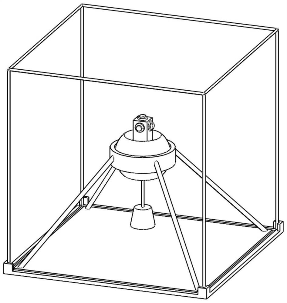
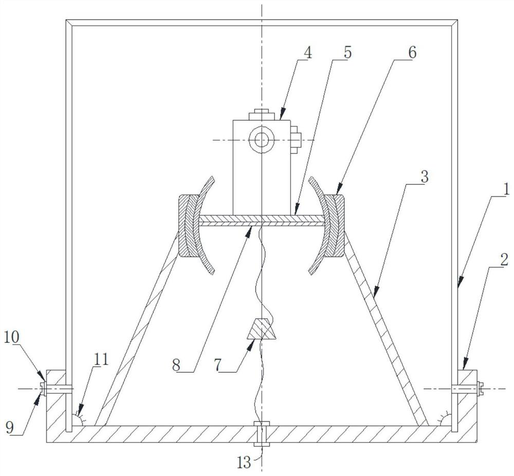
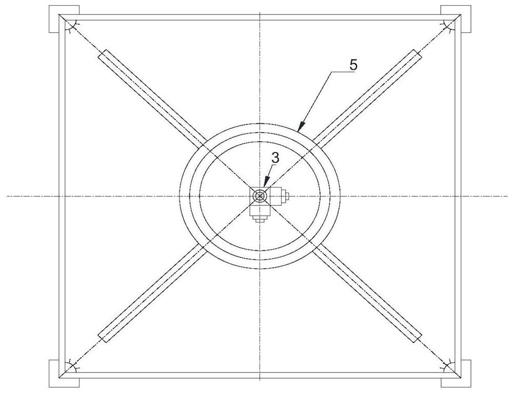
[0046] A device for monitoring spatial displacement in rock and soil based on image recognition, such as Figure 1-7 Shown includes a box body and a spherical bearing 6 located in the box body, three cameras 4, a balance weight 7 and a lighting device 11;

[0047] The box body is a cubic structure, which is composed of an upper base plate, a lower base plate 2, a front side plate, a rear side plate, a left side plate an...


PUM


Abstract

The invention relates to a device and system for monitoring the spatial displacement in a rock-soil body based on image recognition. The device comprises a box body, wherein the box body is of a cubic structure, and the inner surfaces of an upper bottom plate, a front side plate and a right side plate of the box body are provided with grid marks; a spherical bearing located in the box body, wherein the outer ring of the spherical bearing is fixedly connected with the box body, an inner ring of the spherical bearing is a sphere and is provided with a cylindrical through hole, and the central axis of the cylindrical through hole passes through the center of the inner ring and is perpendicular to a horizontal plane; three cameras, wherein the lenses of the three cameras face the upper bottom plate, the front side plate and the right side plate respectively, the central axes are perpendicular to the plates facing the cameras, the three cameras are positioned above the cylindrical through hole and are fixedly connected with the inner ring of the spherical bearing, and each camera is connected with a power line and a transmission line; and a balance weight which is positioned below the cylindrical through hole and is fixedly connected with the inner ring of the spherical bearing. The system comprises more than two above devices and a three-dimensional space grid which is formed by laying by taking the box bodies in the devices as nodes. The device and the system can effectively monitor the spatial displacement in the rock-soil body.

Description

technical field [0001] The invention belongs to the technical field of displacement monitoring and sensing of rock and soil in civil engineering, and relates to a device and system for monitoring spatial displacement in rock and soil based on image recognition, in particular to a method for monitoring and sensing the whole body of soil under the action of external load or environment A device for displacement and its changing tendency. Background technique [0002] In recent years, with the rapid development of the country's economy, it has attached great importance to the economic development of the western region, and more and more investment has been made in the construction of transportation infrastructure in the western region. There are many mountainous areas in the western region, with large ups and downs. It is difficult and costly to build expressways, bridges, and tunnels. Some natural disasters often occur in mountainous areas. Slopes slip under the erosion of ra...

Claims


Application Information

Patent Timeline
Patent Type & Authority Applications(China)
IPC IPC(8): G01B11/02G01B11/16
CPCG01B11/02G01B11/16
Inventor 李忠孟唱朱帅倪嘉卿
Owner SHANGHAI UNIV OF ENG SCI
Why Eureka
Try Eureka