
Distributed optical fiber vibration sensing system and phase carrier demodulation method thereof

A vibration sensing system and distributed optical fiber technology, applied in the field of sensing and detection, can solve the problems of limited application, small dynamic range of interference signal demodulation, and reduced real-time performance of system demodulation, etc., so as to achieve simple optical path structure and improve stability. sexual effect

Active Publication Date: 2021-09-28
TIANJIN UNIV
View PDF13 Cites 3 Cited by
  • Summary
  • Abstract
  • Description
  • Claims
  • Application Information

AI Technical Summary

Problems solved by technology

The introduction of these structures increases the complexity of the distributed optical fiber vibration sensing system and reduces the real-time performance of system demodulation to a certain extent
Although the interferometric optical fiber vibration sensing system has a linear relationship between the interference light intensity and the externally applied vibration signal, it is limited by the shortcomings of the inability to use a single interferometer to locate the structural vibration signal and the small dynamic range of interference signal demodulation. its application in practice

Method used


Image

  • Distributed optical fiber vibration sensing system and phase carrier demodulation method thereof
  • Distributed optical fiber vibration sensing system and phase carrier demodulation method thereof
  • Distributed optical fiber vibration sensing system and phase carrier demodulation method thereof

Examples


Embodiment Construction

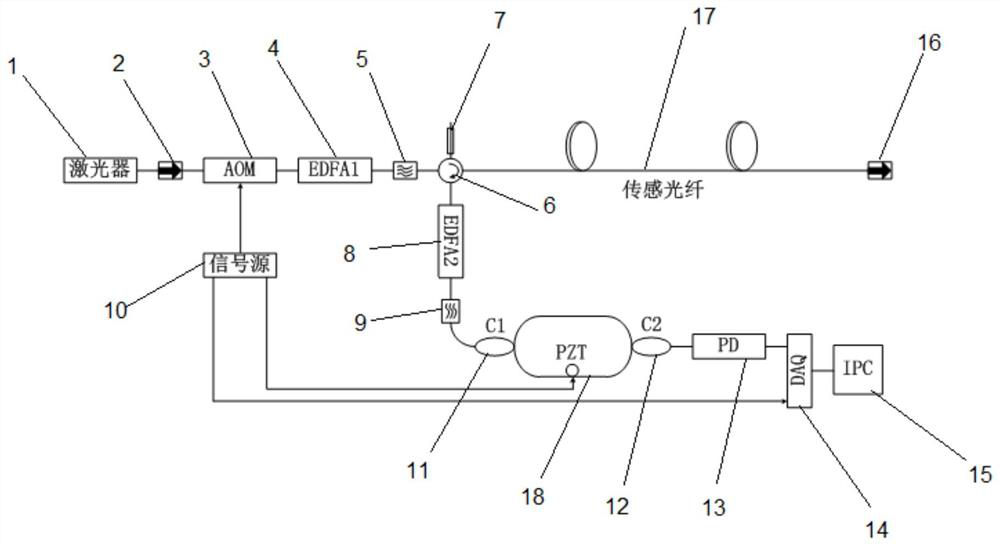
[0044] In order to make the purpose, technical solutions, beneficial effects and significant progress of the embodiments of the present invention clearer, the technical solutions in the embodiments of the present invention will be clearly and completely described below in conjunction with the drawings provided in the embodiments of the present invention, Obviously, all described embodiments are only some embodiments of the present invention, rather than all embodiments; based on the embodiments of the present invention, all other embodiments obtained by those of ordinary skill in the art without making creative work Embodiments all belong to the protection scope of the present invention.

[0045] In the present invention, unless otherwise clearly specified and limited, terms such as "installation", "fixation" and "connection" should be understood in a broad sense, for example, it can be a fixed connection, a detachable connection or a movable connection, or But become one; it ...


PUM


Abstract

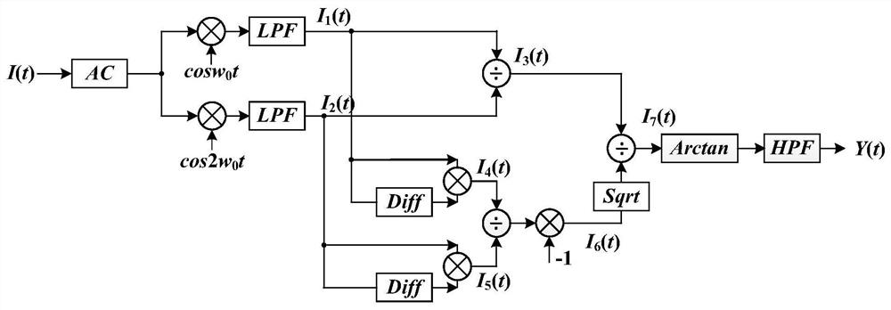
The invention discloses a distributed optical fiber vibration sensing system based on Rayleigh back scattering and Mach-Zehnder interference. The system comprises a phase sensitive optical time domain reflectometer, a one-way Mach-Zehnder optical fiber interferometer, a photoelectric detector and a signal processing unit which are connected in sequence, and also comprises a signal source used for generating a periodic pulse signal and a periodic high-frequency modulation signal; the signal processing unit collects sensing electric signals transmitted back by the photoelectric detector and then analyzes and demodulates the received signals so as to demodulate amplitude-frequency information of vibration signals applied to the sensing optical fiber. The invention also discloses a phase carrier demodulation method, which can effectively realize linear demodulation of a vibration signal applied to the sensing optical fiber by using a phase carrier demodulation technology which is not influenced by interference light intensity and modulation depth.

Description

technical field [0001] The invention belongs to the technical field of sensing and detection, in particular to a distributed optical fiber vibration sensing system based on Rayleigh scattering and Mach-Zehnder interference and a phase carrier demodulation method thereof. Background technique [0002] Distributed optical fiber vibration sensing technology can realize continuous multi-point vibration sensing detection along the line with a single optical fiber link, and its positioning accuracy can be adjusted through hardware parameters such as optical path. Compared with traditional electromagnetic vibration sensing technology, distributed optical fiber vibration sensing technology has many advantages such as simple structure, high sensitivity, and anti-electromagnetic interference. At present, this technology has been successfully applied in perimeter security detection, pipeline security detection, submarine cable fault detection, power line fault detection and many other ...

Claims


Application Information

Patent Timeline
IPC IPC(8): G01H9/00
CPCG01H9/004
Inventor 刘琨刘铁根孙振世江俊峰丁振扬郭海若黄悦朗周子纯薛康
Owner TIANJIN UNIV
Learn More