

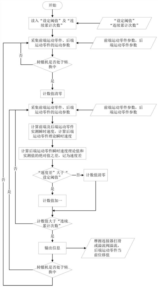
A detection method for the slipping of the friction coupling of the switch machine or the overflow of the relief valve
A detection method and coupling technology, which are used in the testing of machine/structural components, mechanical valve testing, and mechanical component testing, etc., can solve switch failures, switch failures, and reduction of the maximum output force setting value of the action rod, etc. problem, to achieve the effect of preventing jamming failure
- Summary
- Abstract
- Description
- Claims
- Application Information
AI Technical Summary
Problems solved by technology
Method used
Image

Examples
Embodiment 1
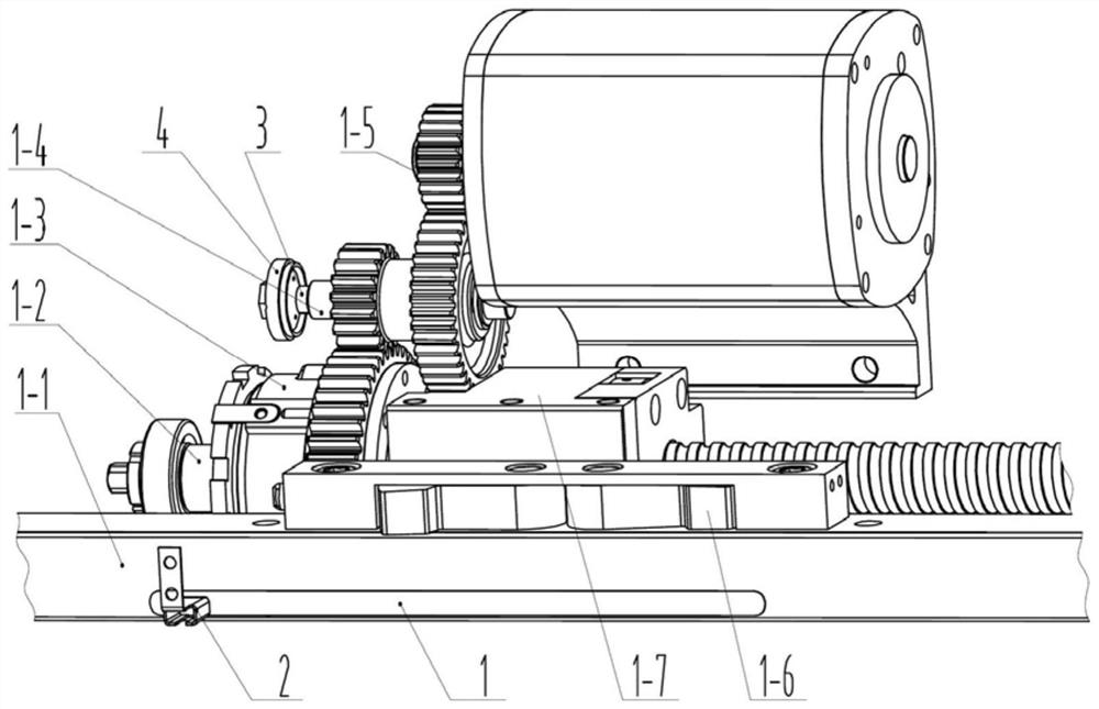
[0032] The invention relates to a detection method for the slippage of a friction coupling of a switch machine or the overflow of an overflow valve, such as figure 1 and figure 2 As shown, the drive locking mechanism of the switch machine is as follows figure 2 , the power output from motor shaft 1-5 is transmitted to A friction connector 1-3 through gear shaft 1-4, A friction connector 1-3 drives ball screw 1-2 to rotate, and ball screw 1-2 drives push plate Sleeve 1-7 moves, the movement process of push plate sleeve 1-7 acts with lock block 1-6, so that lock block 1-6 drives A action rod 1-1 to move, when it moves to the end position, push plate sleeve 1-7 Push the lock block 1-6 to rotate, and lock the A action lever 1-1 at the end position.
[0033] Select A action rod 1-1 as the rear end moving part, select the gear shaft 1-4 as the front end moving part, install the rear end moving part detection piece 1 on the surface of the A action rod 1-1, at a certain distance i...
Embodiment 2
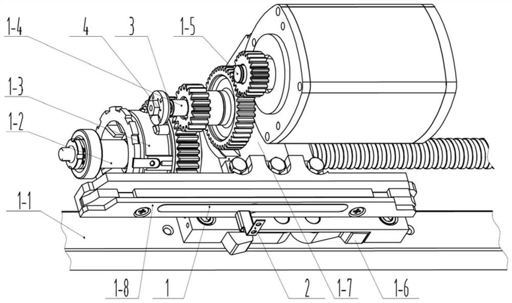
[0052] like figure 1 and image 3 As shown in the figure, the transmission and locking mechanism of the switch machine is the same as that of the first embodiment, the action plates 1-8 are fixedly installed on the push plate sleeves 1-7, the action plates 1-8 are selected as the rear moving parts, and the gear shafts 1-4 are selected. For the front-end moving parts, install the rear-end moving-parts detection part 1 on the surface of the action board 1-8, and install the rear-end moving parts detection head 2 at a certain vertical distance of its motion path, and the two constitute the displacement of the action board 1-8. The sensor, the front-end moving parts detection part 3 is installed on the shaft center of the gear shaft 1-4, and the front-end moving parts detection head 4 is fixedly installed at a certain distance on its axis. The two constitute the gear shaft 1-4 angle sensor, displacement sensor and The data of the rotation angle sensor is input to the data acquisi...
Embodiment 3
[0058] like figure 1 and image 3 As shown in the figure, the transmission and locking mechanism of the switch machine is the same as that of the second embodiment. The action plates 1-8 are selected as the rear-end moving parts, and the motor shafts 1-5 are selected as the front-end moving parts. The front-end moving parts detection part 3 is fixedly installed with the front-end moving parts detection head 4 at a certain distance on its axis, and the two constitute the rotation angle sensors of the motor shafts 1-5, and the rear-end moving parts detection part 1 is installed on the surface of the action plate 1-8. The rear-end moving parts detection head 2 is fixedly installed at a certain vertical distance of its motion path, and the two constitute the action board 1-8 displacement sensors.
[0059] according to image 3 The characteristics of the structural parameters can be seen that if the speed of the motor shaft 1-5 is P (rpm), the gear reduction ratio of the motor sh...
PUM
 Abstract
Description
Claims
Application Information