Pigtail-type optical receptacle

A fiber optic connector, line type technology, applied in optics, light guides, optical components, etc., can solve problems such as space enlargement

Active Publication Date: 2020-11-06
奥比睿株式会社
View PDF11 Cites 0 Cited by
  • Summary
  • Abstract
  • Description
  • Claims
  • Application Information

AI Technical Summary

Problems solved by technology

In addition, in the optical transceiver, the increase in speed is required with the increase of IP traffic, and the space required for the circuit is increased with the increase in the modulation speed of the optical signal emitted from the optical element.

Method used


Image

  • Pigtail-type optical receptacle
  • Pigtail-type optical receptacle
  • Pigtail-type optical receptacle

Examples


no. 1 Embodiment approach

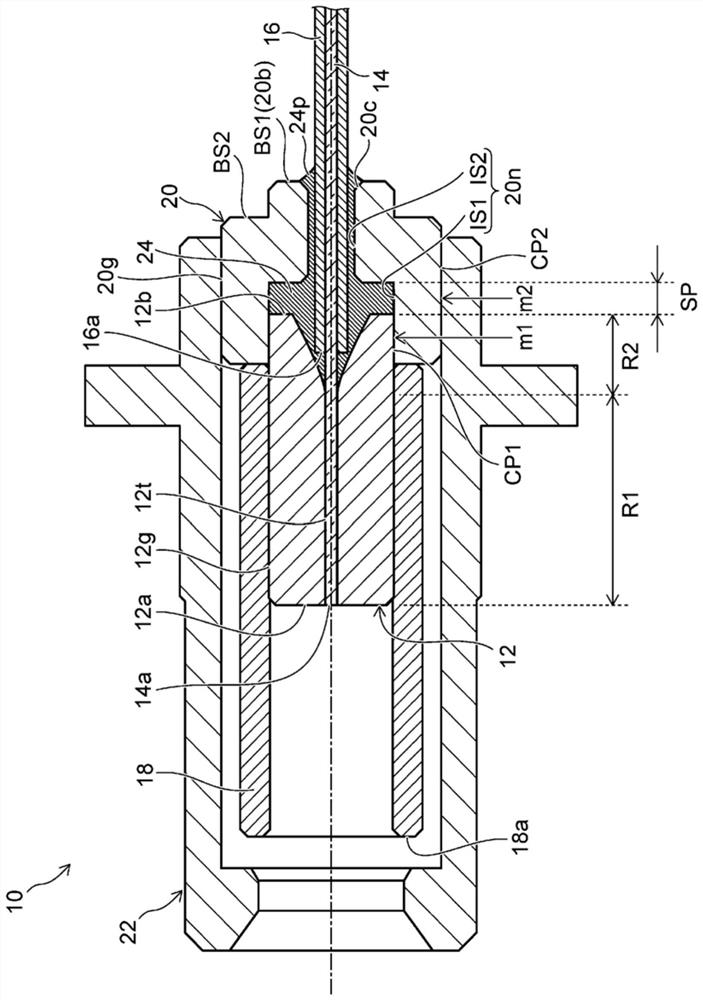
[0096] figure 1 It is a sectional view showing the pigtail type optical fiber connector according to the first embodiment.

[0097] Such as figure 1 As shown, a pigtail type optical fiber connector (hereinafter referred to as an optical fiber connector) 10 includes a ferrule 12 , an optical fiber 14 , a protective member 16 , a sleeve 18 , a holder 20 , and an accommodating portion 22 .

[0098] The sleeve 12 has a cylindrical shape having a through-hole 12t extending in the axial direction. The through hole 12t passes through between the top end 12a and the rear end 12b of the sleeve 12 in a straight line. The optical fiber 14 extends laterally from the rear end 12 b of the ferrule 12 to the outside of the ferrule 12 while being held by the ferrule 12 while being inserted into the through hole 12 t . In other words, ferrule 12 holds one end of optical fiber 14 .

[0099] The optical fiber 14 is inserted into substantially the entirety of the through hole 12t. The tip 14a...

no. 2 Embodiment approach

[0162] Figure 5 It is a sectional view showing a pigtail type optical fiber connector according to the second embodiment.

[0163] Such as Figure 5 As shown, in the optical fiber connector 100, the outer surface 120g of the holder 120 has a first outer peripheral portion OS1 and a second outer peripheral portion OS2.

[0164] The first outer peripheral portion OS1 is held by the housing portion 22 . The outer diameter of the first outer peripheral portion OS1 of the holder 120 is substantially the same as the inner diameter of the housing portion 22 . For example, the holder 120 is held by the accommodating portion 22 by press-fitting a portion of the first outer peripheral portion OS1 into the accommodating portion 22 .

[0165] The second outer peripheral portion OS2 is provided at the distal end portion of the holder 120 . The second outer peripheral portion OS2 is provided, for example, in front of the first outer peripheral portion OS1 , continues to the first outer...

no. 3 Embodiment approach

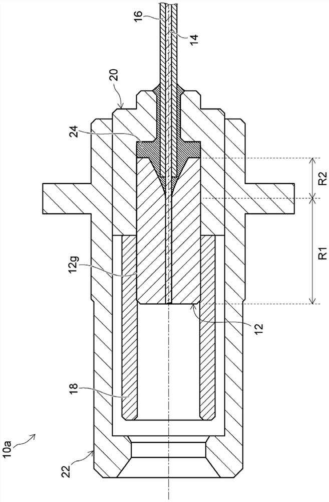
[0184] Figure 9 It is a cross-sectional view showing a pigtail type optical fiber connector according to the third embodiment.

[0185] Such as Figure 9 As shown, in the optical fiber connector 200 , the receiving portion 222 is mounted on the tip side of the holder 220 .

[0186] The holder 220 has a mounting portion 220 a for mounting the receiving portion 222 . The mounting portion 220 a is provided at the top end portion of the holder 220 . The receiving portion 222 has a mounted portion 222 a attached to the mounting portion 220 a of the receiving portion 222 . The mounted portion 222 a is provided at the rear end portion of the housing portion 222 . The mounting part 220a and the mounted part 222a are cylindrical. The mounted portion 222a is fitted on the outside of the mounting portion 220a. Thus, the receiving portion 222 is attached to the distal end side of the holder 220 .

[0187] The holder 220 has a flange portion 220f. The flange portion 220f is provid...


PUM


Abstract

A pigtail-type optical receptacle is provided and includes a tubular ferrule having a through-hole extending in an axial direction, an optical fiber inserted into the through-hole such that part of the optical fiber extends outside the ferrule, a protective member covering the part of the optical fiber extending outside the ferrule, a tubular sleeve mounted on a front end side, outer surface of the ferrule, a holder tubular having holding the rear end side of the ferrule, and a tubular housing covering the ferrule and at least a portion of the sleeve. The ferrule through-hole includes first and second regions, the second region being disposed rearward of the first region, and the housing engaging the outer surface of the holder rearward of the first region. As a result, the pigtail-type optical receptacle that can be reduced in size without deteriorating reliability is provided.

Description

[0001] This application is a divisional application of the invention patent application with the application date of May 19, 2017, the invention name is "pigtail type optical fiber connector", and the national application number is "201780017201.4". technical field [0002] Aspects of the invention generally relate to a pigtail type fiber optic connector. Background technique [0003] An optical fiber connector is used in an optical module of a transceiver for optical communication as a component for optically connecting an optical fiber connector to optical elements such as a light receiving element and a light emitting element. In addition, among such optical fiber connectors, a pigtail type optical fiber connector in which an optical fiber is drawn out from a ferrule is also known. [0004] For example, Patent Document 1 proposes a pigtail-type optical fiber connector. By holding the ferrule holding the optical fiber in the holder and pressing the holder into the housing ...

Claims


Application Information

Patent Timeline
Patent Type & Authority Applications(China)
IPC IPC(8): G02B6/38
CPCG02B6/3807G02B6/3833G02B6/3847G02B6/3837G02B6/3874G02B6/4285G02B6/4292G02B6/3869G02B6/4262
Inventor 冨永康平兼行哲史近藤祥我妻弘嗣箱崎悟史佐藤裕希
Owner 奥比睿株式会社
Why Eureka
Try Eureka