A Continuous Zoom Optical System with External Entrance Pupil

An optical system and light technology, applied in the field of continuous zoom optical system, can solve the problems of not having continuous zoom function, not having built-in diaphragm, not having external entrance pupil, etc., achieving small system size, compact structure, and changing center of mass small effect

Active Publication Date: 2022-05-10
XI'AN INST OF OPTICS & FINE MECHANICS - CHINESE ACAD OF SCI
View PDF7 Cites 0 Cited by
  • Summary
  • Abstract
  • Description
  • Claims
  • Application Information

AI Technical Summary

Problems solved by technology

[0010] In order to solve the existing optical system, either the diaphragm is built-in, without an external entrance pupil; or, the pupil is external, but does not have a built-in diaphragm; or, the diaphragm is located in the moving group, and the system structure is complicated; or, there is An external entrance pupil, but does not have a continuous zoom function; or, the working band is the infrared spectrum, and the technical problem of low imaging resolution, the present invention provides a continuous zoom optical system with an external entrance pupil

Method used


Image

  • A Continuous Zoom Optical System with External Entrance Pupil
  • A Continuous Zoom Optical System with External Entrance Pupil
  • A Continuous Zoom Optical System with External Entrance Pupil

Examples


Embodiment 1

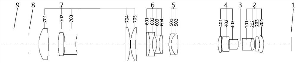
[0069] Such as figure 1 As shown, a continuous zoom optical system with an external entrance pupil defines that the light is incident from left to right. Group 6, compensation mirror group 5, relay mirror group 4, diaphragm 3 and rear fixed mirror group 2; the left side of the front fixed mirror group 7 is the object plane 9 of the optical system, and the right side of the rear fixed mirror group 2 is the optical The image plane 1 (focal plane) of the system; the entrance pupil 8 of the optical system is fixed on the left side of the front fixed lens group 7 and on the right side of the object plane 9, and the front and rear positions are stable during zooming; the variable power lens group 6 and the light The diaphragm 3, the front fixed mirror group 7, the compensation mirror group 5, the relay mirror group 4 and the rear fixed mirror group 2 together constitute a complete imaging system.

[0070] The variable power mirror group 6 and the compensation mirror group 5 can mov...

Embodiment 2

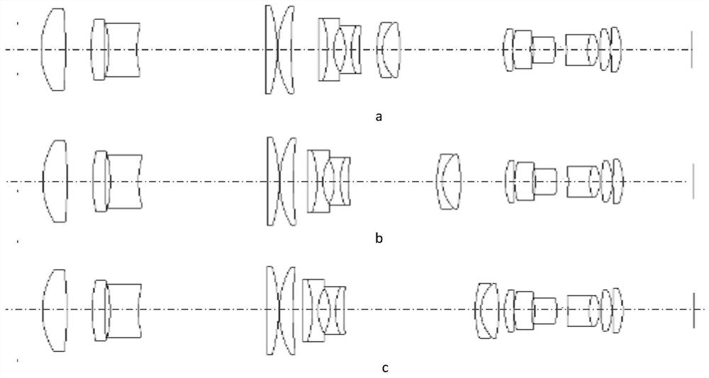
[0132] The difference from Embodiment 1 is that: Figure 7 As shown, the first plane mirror 10 is set between the first negative lens 703 and the third positive lens 704; the second plane mirror 11 is set between the thirteenth positive lens 204 and the image plane 1; each lens surface type The parameter value remains the same, the position is adjusted accordingly, Figure 7 Among them, figure a is a schematic diagram of lens group distribution under telephoto, and figure b is a schematic diagram of lens group distribution under short focus. The plane mirror can change the propagation direction of the light beam, compress the volume of the entire optical system, and further realize miniaturization and dexterity. In other embodiments, only the first plane mirror 10 or only the second plane mirror 11 can be provided .


PUM


Abstract

The present invention provides a continuous zoom optical system with an external entrance pupil, which solves the problem that the existing optical system either does not have an external entrance pupil; or does not have a built-in diaphragm; or has a complicated system structure; or does not have a continuous zoom function; or Technical problem with low imaging resolution. The optical system includes a front fixed lens group with a positive refractive power, a zoom lens group with a negative refractive power, a compensation lens group, a relay lens group with a positive refractive power, a diaphragm and a focal power of Positive rear fixed lens group; set the focal length of the zoom lens group to f6, the focal length of the telephoto position of the optical system is fL, f6 and fL satisfy the following conditional formula: 10.2<|fL / f4|<23.6; the focal length of the compensation lens group is Positively, suppose the radial magnification of the compensation group at the telephoto position of the optical system is m5, and m5 satisfies the following conditional formula: 1.6<|m5|<6.5; the zoom lens group and the compensation lens group move back and forth along the optical axis synchronously, Achieve continuous zoom.

Description

technical field [0001] The invention relates to a continuous zoom optical system, in particular to a continuous zoom optical system with a built-in aperture, an external entrance pupil and adapted to a high-resolution image sensor. Background technique [0002] Compared with infrared imaging detection systems with large pixel sizes, visible-band optical systems using small-sized photoelectric imaging devices such as CCD or CMOS can more easily obtain high imaging resolution. Wider range of applications. [0003] The optical system with an external entrance pupil can independently complete the optical imaging function, and can also be combined with an afocal optical system to form an optical system with a longer focal length or a larger field of view to realize the modularization of the optical system; the built-in aperture diaphragm can also It can be adjusted manually or automatically to adapt to a larger illuminance range; in addition, the optical system with an external ...

Claims


Application Information

Patent Timeline
Patent Type & Authority Patents(China)
IPC IPC(8): G02B15/14
CPCG02B15/145129
Inventor 曲锐郭惠楠曹剑中陈卫宁
Owner XI'AN INST OF OPTICS & FINE MECHANICS - CHINESE ACAD OF SCI
Why Eureka
Try Eureka