
Laser light source device and projection system

A laser light source and laser technology, applied in the field of projection display, can solve the problems of uneven mixing, large spot size, affecting homogenization effect and display effect, etc.

Pending Publication Date: 2021-09-28
QINGDAO HISENSE LASER DISPLAY CO LTD
View PDF0 Cites 1 Cited by
  • Summary
  • Abstract
  • Description
  • Claims
  • Application Information

AI Technical Summary

Problems solved by technology

The spot size of lasers of different colors is large after combining light, and the mixing is uneven, which affects the subsequent homogenization effect and display effect

Method used


Image

  • Laser light source device and projection system
  • Laser light source device and projection system
  • Laser light source device and projection system

Examples


Embodiment Construction

[0016] In order to make the above objects, features and advantages of the present invention more comprehensible, the present invention will be further described below in conjunction with the accompanying drawings and embodiments. Example embodiments may, however, be embodied in many forms and should not be construed as limited to the embodiments set forth herein; rather, these embodiments are provided so that this disclosure will be thorough and complete, and will fully convey the concept of example embodiments to those skilled in the art. The same reference numerals denote the same or similar structures in the drawings, and thus their repeated descriptions will be omitted. The words expressing position and direction described in the present invention are all described by taking the accompanying drawings as an example, but changes can also be made according to needs, and all changes are included in the protection scope of the present invention. The drawings of the present inv...


PUM


Abstract

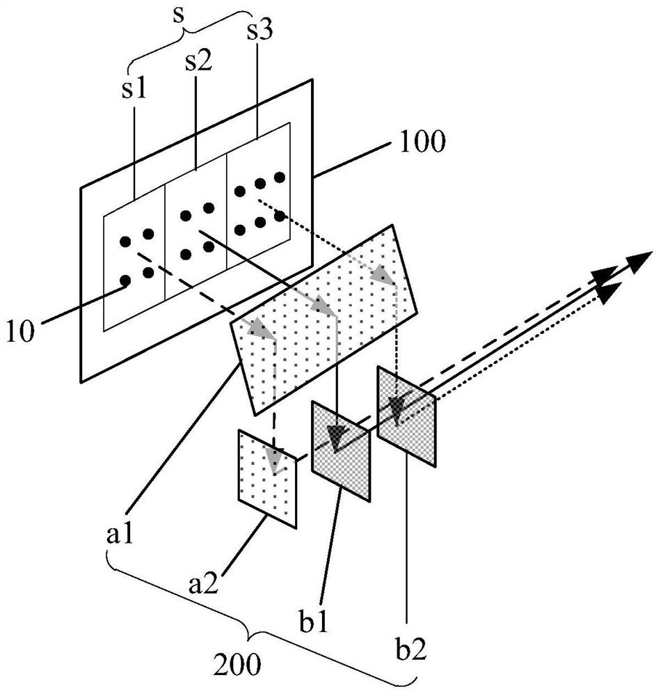
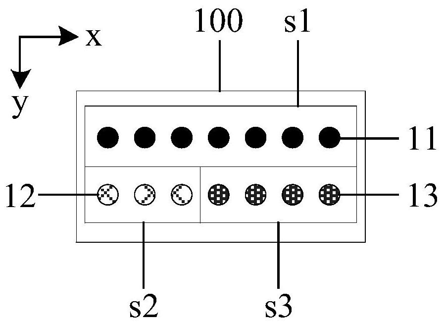
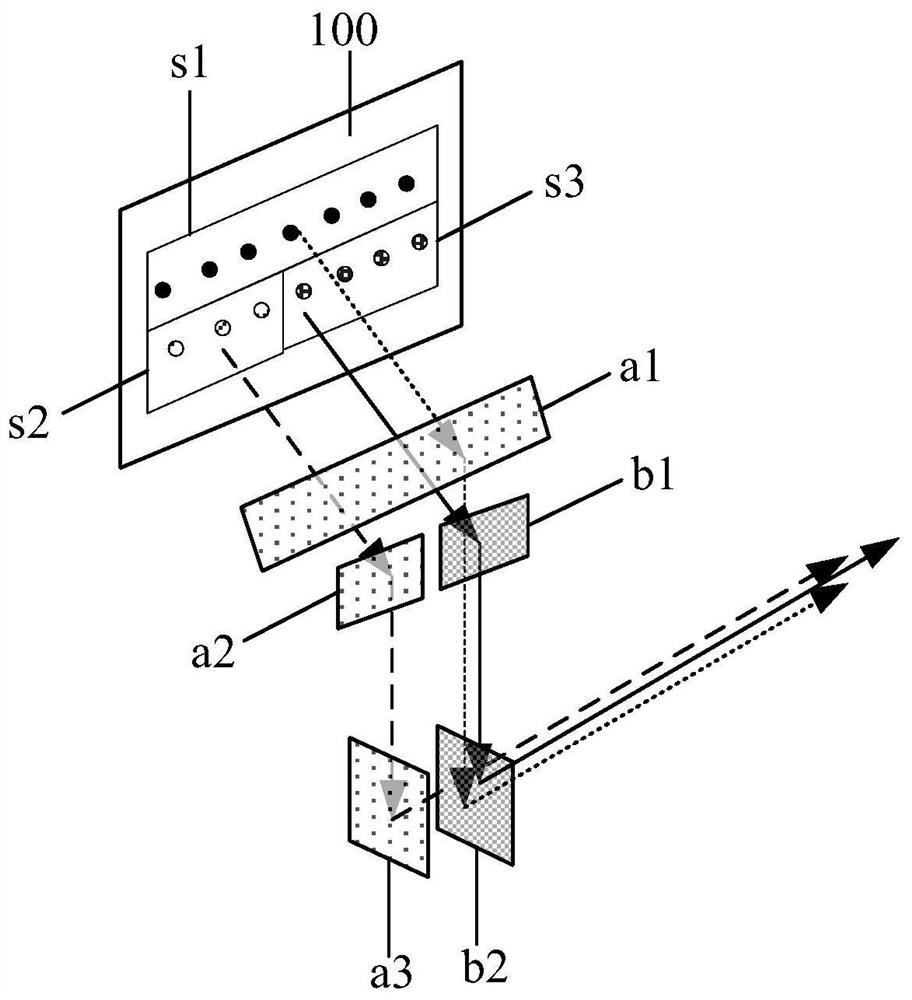
The invention discloses a laser light source device and a projection system. The laser light source device comprises a laser and a light combining assembly, wherein the laser comprises a first laser chip, a second laser chip and a third laser chip which emit laser with different wavelengths, the laser chips with the same color are arranged into a laser chip group, and the laser chips are arranged into a matrix; and the light combining assembly is positioned on the light emitting side of the laser and is used for enabling the laser beams with different colors emitted by each laser chip group to be converted and beam to the same position through a light path and then to be emitted in a set direction. The light combining assembly comprises a reflector and a light combining mirror, the laser beams are subjected to light path turning through the reflector, the laser beams with different colors are combined through the light combining mirror, and finally the laser beams emitted by the laser chip groups are combined to the same position, so that the positions of laser spots with different colors are overlapped, the spot size is reduced, and the lasers with different colors are mixed more sufficiently.

Description

technical field [0001] The invention relates to the technical field of projection display, in particular to a laser light source device and a projection system. Background technique [0002] At present, the laser projection industry is developing very rapidly, and lasers, as one of the core components, play an irreplaceable role. Semiconductor lasers are packaged after the chip is produced. [0003] Due to its small footprint, the compact laser (Multi Chip LD, referred to as MCL) is conducive to the development of miniaturization of laser light source modules, and is the development trend of laser projection systems. MCL lasers have the advantages of long life, high brightness, and high power. MCL lasers can replace multiple BANK lasers, and chips with different colors of outgoing light can be packaged inside the same MCL laser, thereby realizing the functions of multiple monochromatic lasers. [0004] Due to the difference in the number and arrangement of light-emitting c...

Claims


Application Information

Patent Timeline
IPC IPC(8): G03B21/20G02B27/14G02B27/10
CPCG03B21/2013G03B21/2033G03B21/2066G03B21/2073G03B21/208G02B27/14G02B27/1006
Inventor 罗李浩男李巍
Owner QINGDAO HISENSE LASER DISPLAY CO LTD
Learn More