Check patentability & draft patents in minutes with Patsnap Eureka AI!

Terminal structure

A terminal structure and terminal technology, applied in electrical equipment structural parts, coupling devices, electric vehicles, etc., can solve the problems of low heat dissipation efficiency and complex terminal structure, and achieve the effect of improving heat dissipation efficiency

Active Publication Date: 2021-09-28
ZHEJIANG GEELY HLDG GRP CO LTD +1
View PDF5 Cites 1 Cited by
  • Summary
  • Abstract
  • Description
  • Claims
  • Application Information

AI Technical Summary

Problems solved by technology

[0005] The present invention provides a terminal structure to solve the problems that the liquid cooling method in the prior art makes the structure of the terminal complicated and the heat dissipation efficiency low

Method used


Image

  • Terminal structure
  • Terminal structure
  • Terminal structure

Examples


Embodiment

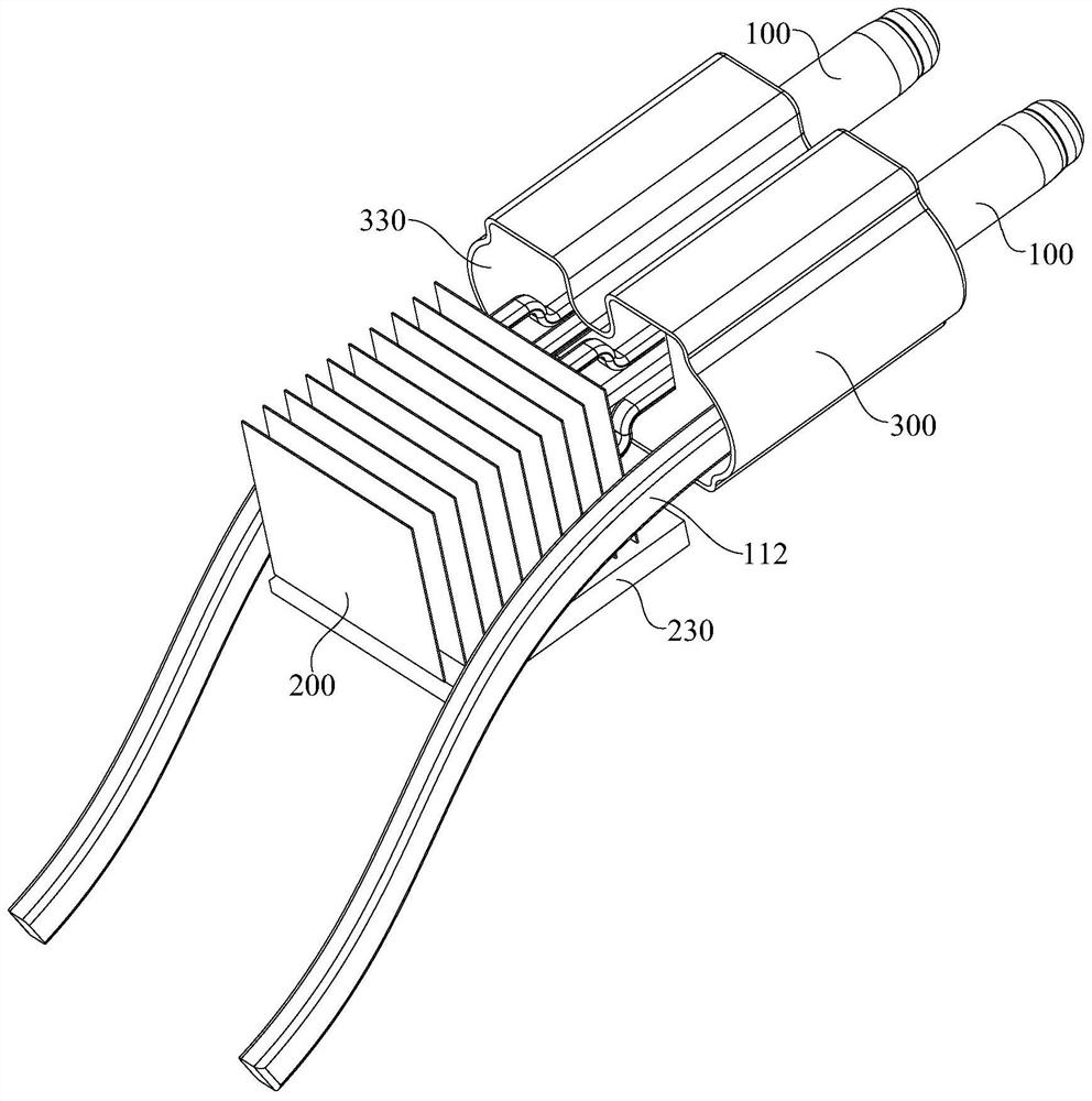
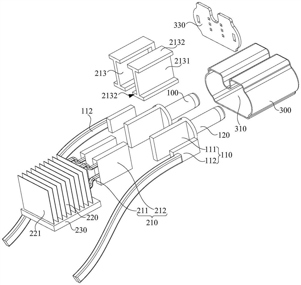
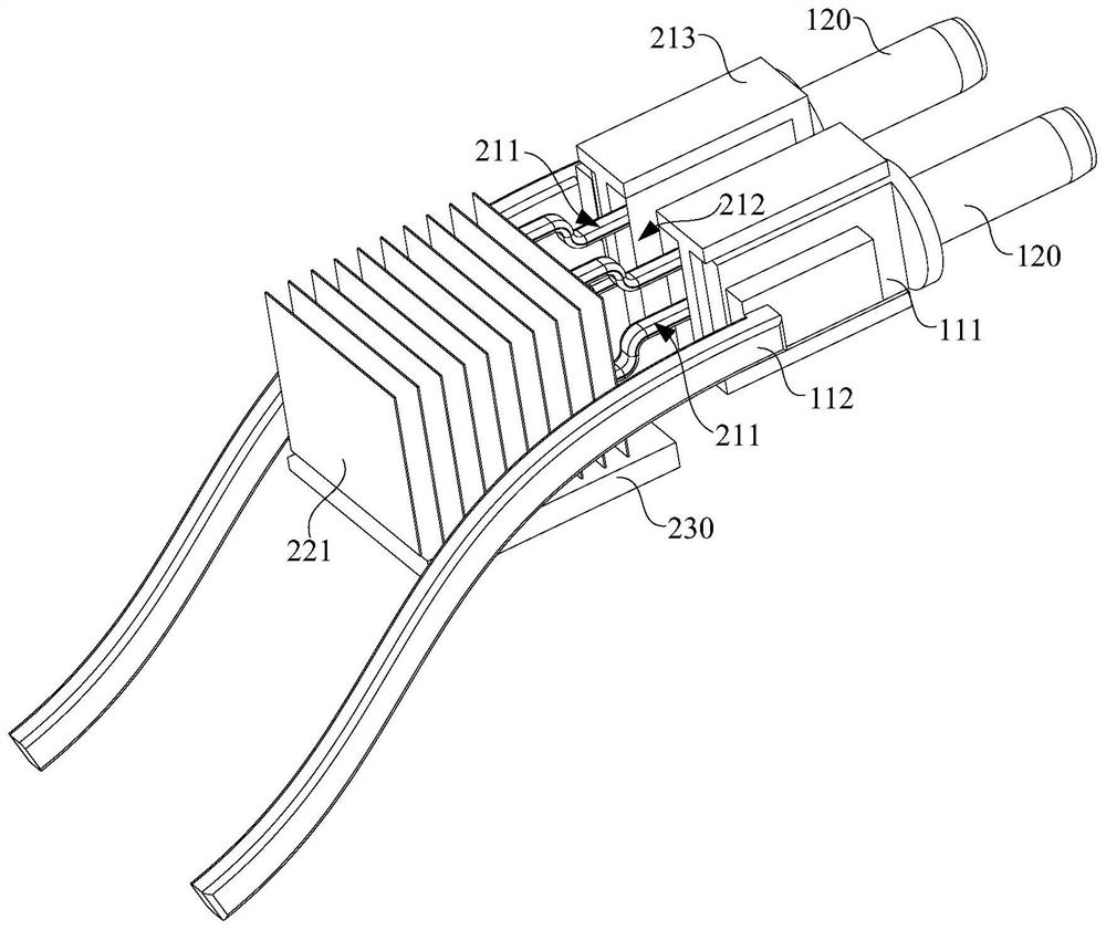
[0051] figure 1 A schematic diagram of the terminal structure provided by the present invention, figure 2 for figure 1 schematic diagram of the explosion, image 3 It is a schematic diagram of the connection between the terminal and the heat sink in the terminal structure provided by the present invention.

[0052] Such as Figure 1-3 As shown, the present application provides a terminal structure, including: a terminal 100, the terminal 100 includes a connection end 110 and a plug end 120 connected to the connection end 110, the connection end 110 is used for electrical connection with a conductor, and the plug end 120 is used for Electrically connected with the mating interface; heat sink 200, heat sink 200 includes a heat transfer assembly 210 and a heat sink 220 connected to the heat transfer assembly 210, the heat transfer assembly 210 is connected to the connection end 110, so as to transfer the heat of the terminal 100 to the heat sink 220 , to dissipate heat from ...


PUM


Abstract

The invention provides a terminal structure, which comprises a terminal, a heat dissipation device and a shell, wherein the terminal comprises a connecting end and a plugging end connected with the connecting end, the connecting end is used for being electrically connected with a conductor, and the plugging end is used for being electrically connected with a pairing interface; the heat dissipation device comprises a heat transfer assembly and a radiator connected with the heat transfer assembly, and the heat transfer assembly is connected with the connecting end to transfer heat of the terminal to the radiator so as to dissipate heat of the terminal; and the shell is provided with a containing cavity, the connecting end and the heat transfer assembly are partially located in the containing cavity, and the plugging end and the radiator are located outside the containing cavity. The terminal structure provided by the invention is simple in structure and relatively high in heat dissipation efficiency.

Description

technical field [0001] The invention relates to the technical field of electric vehicle charging, in particular to a terminal structure. Background technique [0002] In order to meet the needs of long-range charging and fast power replenishment of electric vehicles, the trend of using high-power charging technology to charge electric vehicles is becoming more and more obvious. [0003] High-power charging technology mainly refers to increasing the output power of the charging station to increase the output current of the charging station, so that the battery power of the electric vehicle can be restored to more than 80% in a short time to achieve faster energy replenishment. Due to the large output current in a short period of time, when the charging gun connected to the charging station is plugged into the charging socket connected to the battery of the electric vehicle, a great deal of heat will be generated at the positions of the terminals on the two. And the temperatu...

Claims


Application Information

Patent Timeline
IPC IPC(8): H01R13/533H05K7/20H01R13/04H01R13/10B60L53/16
CPCH01R13/533H05K7/2039H05K7/20145H01R13/04H01R13/10B60L53/16Y02T90/14
Inventor 何英勇王伟郭水保石志超杨康纪克
Owner ZHEJIANG GEELY HLDG GRP CO LTD
Features
  • R&D
  • Intellectual Property
  • Life Sciences
  • Materials
  • Tech Scout
  • Unparalleled Data Quality
  • Higher Quality Content
  • 60% Fewer Hallucinations
Learn More