
Vertical cavity surface-emitting laser and preparation method thereof

A vertical cavity surface emission, laser technology, applied in lasers, laser parts, semiconductor lasers, etc., can solve the problems of difficult to meet the application requirements of narrow linewidth of lasers, affecting the performance and stability of laser devices, and large spectral linewidth, etc. Achieve the effect of improving device performance and reliability, increasing the effective cavity length, and expanding the application range

Pending Publication Date: 2021-09-28
VERTILITE CO LTD
View PDF5 Cites 1 Cited by
  • Summary
  • Abstract
  • Description
  • Claims
  • Application Information

AI Technical Summary

Problems solved by technology

[0003] In view of this, the embodiment of the present invention provides a vertical cavity surface emitting laser and its preparation method, which solves the problem that the vertical cavity surface emitting laser has a short cavity length and a large spectral linewidth in the prior art, which affects the device performance of the laser. and stability, it is difficult to meet the technical problems of narrow linewidth application requirements of vertical cavity surface emitting lasers

Method used


Image

  • Vertical cavity surface-emitting laser and preparation method thereof
  • Vertical cavity surface-emitting laser and preparation method thereof
  • Vertical cavity surface-emitting laser and preparation method thereof

Examples


Embodiment

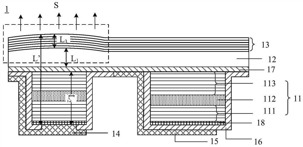
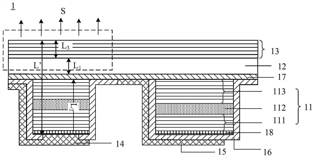
[0029] An embodiment of the present invention provides a vertical cavity surface emitting laser. figure 1 A schematic cross-sectional structure diagram of a vertical cavity surface emitting laser provided by an embodiment of the present invention. Such as figure 1 As shown, the vertical cavity surface emitting laser comprises a laser resonator structure 1; the laser resonator structure 1 comprises a laser cavity 11, a substrate 12 and an external cavity resonator 13 arranged in layers; along the outgoing direction of the laser beam (such as figure 1 shown in the S direction), the effective cavity length L' of the vertical cavity surface emitting laser includes the thickness L of the laser cavity 2 , the thickness of the substrate L 1 and the thickness L of the external cavity resonator 3 ; The outgoing direction of the laser beam is parallel to the direction in which the substrate 12 points to the external cavity resonator 13 .

[0030] Exemplarily, the spectral line width...


PUM

PropertyMeasurementUnit
thicknessaaaaaaaaaa

Abstract

The embodiment of the invention discloses a vertical cavity surface-emitting laser and a preparation method thereof. The vertical cavity surface-emitting laser comprises a laser resonant cavity structure; the laser resonant cavity structure comprises a laser cavity, a substrate and an outer cavity resonant cavity which are arranged in a laminated mode; the effective cavity length of the vertical cavity surface-emitting laser comprises the thickness of the laser cavity, the thickness of the substrate and the thickness of the outer cavity resonant cavity in the emergent direction of a laser beam. and the emitting direction of the laser beam is parallel to the direction of the substrate pointing to the outer cavity resonant cavity. In the prior art, a vertical cavity surface-emitting laser is short in cavity length and large in spectral line width, the device performance and stability of the laser are affected, and the narrow line width application requirement of the vertical cavity surface-emitting laser is difficult to meet. With the laser of the invention adopted, the above technical problems can be solved.

Description

technical field [0001] Embodiments of the present invention relate to the technical field of semiconductor lasers, in particular to a vertical cavity surface emitting laser and a manufacturing method thereof. Background technique [0002] Vertical-Cavity Surface-Emitting Laser (Vertical-Cavity Surface-Emitting Laser, referred to as VCSEL, also translated as Vertical-Cavity Surface-Emitting Laser) is a semiconductor, and its outgoing laser is emitted perpendicular to the top surface. Due to the short range of the cavity length of the traditional VCSEL, usually around 1.5 microns, the spectral linewidth (Full Width at Half Maxima, referred to as FWHM) is large, that is, FWHM>100MHz, which affects the device performance and stability of the laser, and it is difficult to meet the vertical Narrow linewidth application requirements for cavity surface emitting lasers. Contents of the invention [0003] In view of this, the embodiment of the present invention provides a vertic...

Claims


Application Information

Patent Timeline
Patent Type & Authority Applications(China)
IPC IPC(8): H01S5/183H01S5/14
CPCH01S5/183H01S5/18361H01S5/14
Inventor 寇君龙饶志龙
Owner VERTILITE CO LTD
Learn More