
Dynamic control conversion circuit

A technology for dynamically controlling and converting circuits, which is applied in the direction of logic circuits, logic circuit interface devices, logic circuit connection/interface layout, etc., can solve the problems of large occupied area, complex circuit structure, high production cost, etc., and achieve low area occupation and improved Stability and reliability, the effect of simple structure

Pending Publication Date: 2021-09-28
CHANGXIN MEMORY TECH (SHANGHAI) INC
View PDF0 Cites 2 Cited by
  • Summary
  • Abstract
  • Description
  • Claims
  • Application Information

AI Technical Summary

Problems solved by technology

[0003] The purpose of the present disclosure is to provide a dynamic control conversion circuit, and then at least to a certain extent overcome technical problems such as complex circuit structure, high production cost, and large occupied area caused by the limitations and defects of related technologies

Method used


Image

  • Dynamic control conversion circuit
  • Dynamic control conversion circuit
  • Dynamic control conversion circuit

Examples


Embodiment Construction

[0050] Example embodiments will now be described more fully with reference to the accompanying drawings. Example embodiments may, however, be embodied in many forms and should not be construed as limited to the embodiments set forth herein; rather, these embodiments are provided so that this disclosure will be thorough and complete, and will fully convey the concept of example embodiments to those skilled in the art. The same reference numerals in the drawings denote the same or similar structures, and thus their detailed descriptions will be omitted.

[0051] Although relative terms such as "upper" and "lower" are used in this specification to describe the relative relationship of one component of an icon to another component, these terms are used in this specification only for convenience, for example, according to the description in the accompanying drawings directions for the example described above. It will be appreciated that if the illustrated device is turned over so...


PUM


Abstract

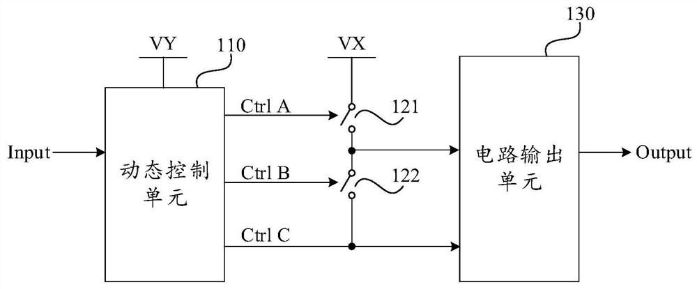
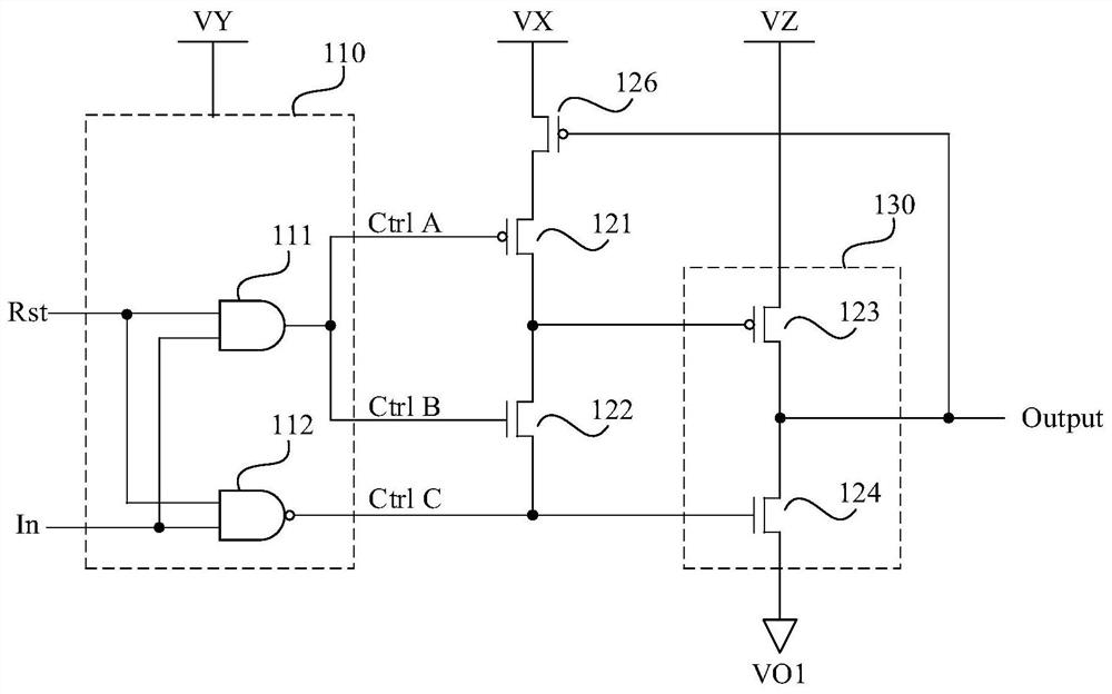
The invention relates to the technical field of semiconductors, in particular to a dynamic control conversion circuit. The circuit comprises a dynamic control unit which is used for generating a dynamic control signal according to a received input signal; a first semiconductor switch the control end of which is connected with the first signal output end of the dynamic control unit, and the first end of which is connected with a first voltage end; a second semiconductor switch the control end of which is connected with the second signal output end of the dynamic control unit; and a circuit output unit the first control end of which is connected with the second end of the first semiconductor switch and the first end of the second semiconductor switch, and the second control end of which is connected with the second end of the second semiconductor switch and the third signal output end of the dynamic control unit. According to the circuit, the problem of switch competition can be effectively avoided, and the dynamic conversion control of potential signals can be realized only by using very small area occupation and very low production cost.

Description

technical field [0001] The present disclosure relates to the technical field of semiconductors, in particular to a dynamic control conversion circuit. Background technique [0002] When designing an integrated circuit, it is often encountered that a potential conversion of a voltage signal is required. For example, when the working voltage requirements are different, it is necessary to convert and adjust the voltage signal in time. In the prior art, a conversion chip with a complex structure is generally used as an intermediate transmission circuit to realize potential conversion. However, traditional conversion chips not only have high production costs, but also occupy a large area, which seriously affects the performance of integrated circuits. Contents of the invention [0003] The purpose of the present disclosure is to provide a dynamic control conversion circuit, and then at least to a certain extent overcome technical problems such as complex circuit structure, hig...

Claims


Application Information

Patent Timeline
IPC IPC(8): H03K19/0175H03K19/0185
CPCH03K19/017509H03K19/018507H03K19/0175H03K19/0185H03K19/018521
Inventor 尚为兵池性洙汪瑛
Owner CHANGXIN MEMORY TECH (SHANGHAI) INC
Learn More