
Adjustable intelligent processing equipment for jewelry inlaying

An intelligent processing and adjustable technology, applied in jewelry, etc., can solve the problems of clamping block conversion, poor clamping effect, sliding jewelry, etc., to achieve the effect of ensuring stability, facilitating processing, and increasing the scope of use

Pending Publication Date: 2021-10-01
深圳市冠泰珠宝有限公司
View PDF6 Cites 0 Cited by
  • Summary
  • Abstract
  • Description
  • Claims
  • Application Information

AI Technical Summary

Problems solved by technology

[0003] The purpose of the present invention is to at least solve one of the technical problems in the prior art, and provide an adjustable intelligent processing equipment for jewelry inlays, which can solve the problem of poor clamping effect and the inability to perform clamping on the clamping block according to the shape of the jewelry. conversion, which in turn can easily lead to problems with jewelry sliding

Method used


Image

  • Adjustable intelligent processing equipment for jewelry inlaying
  • Adjustable intelligent processing equipment for jewelry inlaying
  • Adjustable intelligent processing equipment for jewelry inlaying

Examples


Embodiment 1

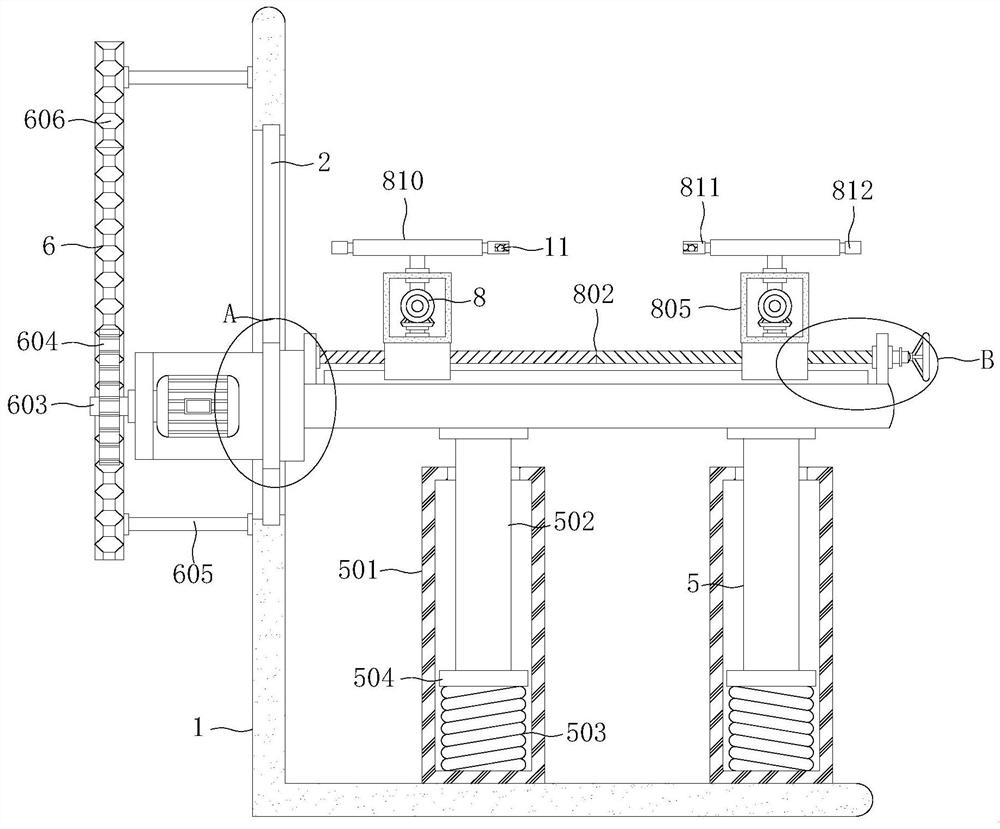
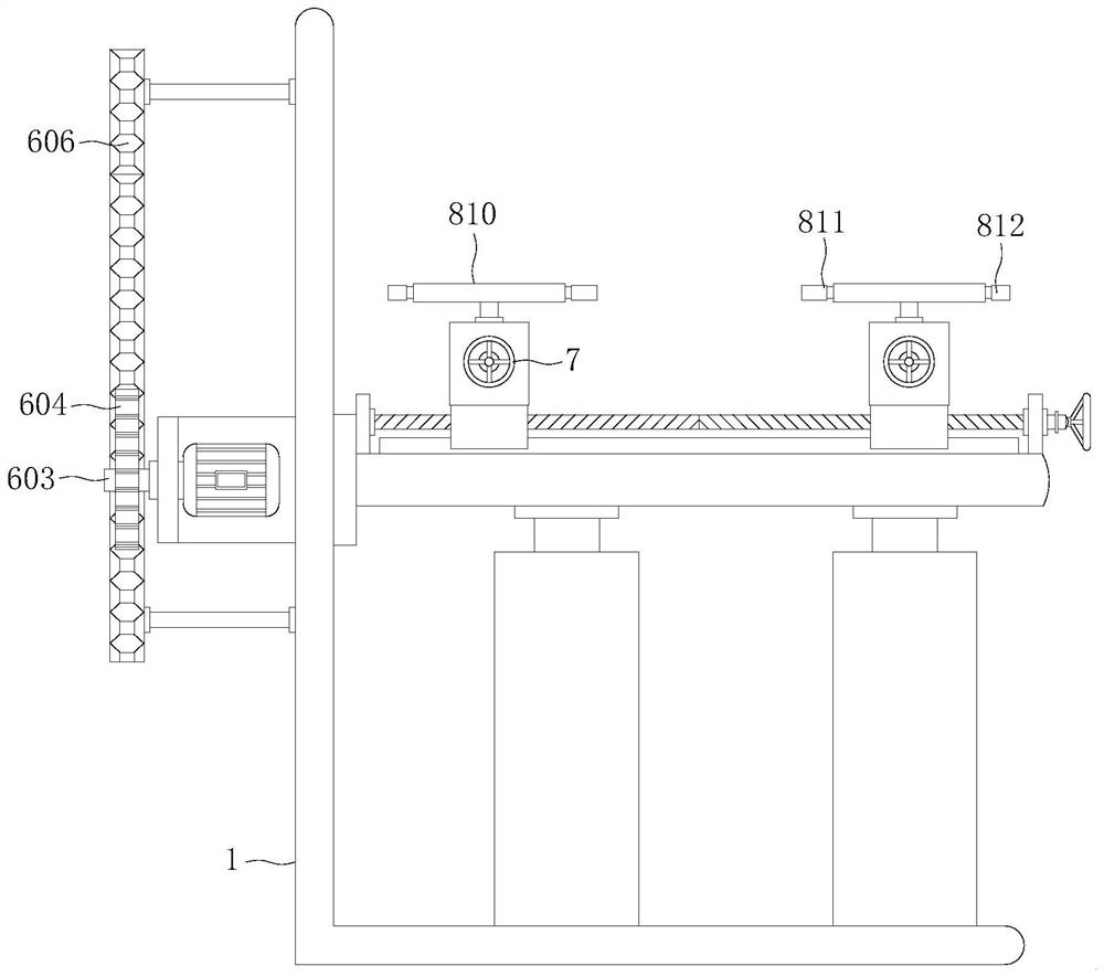
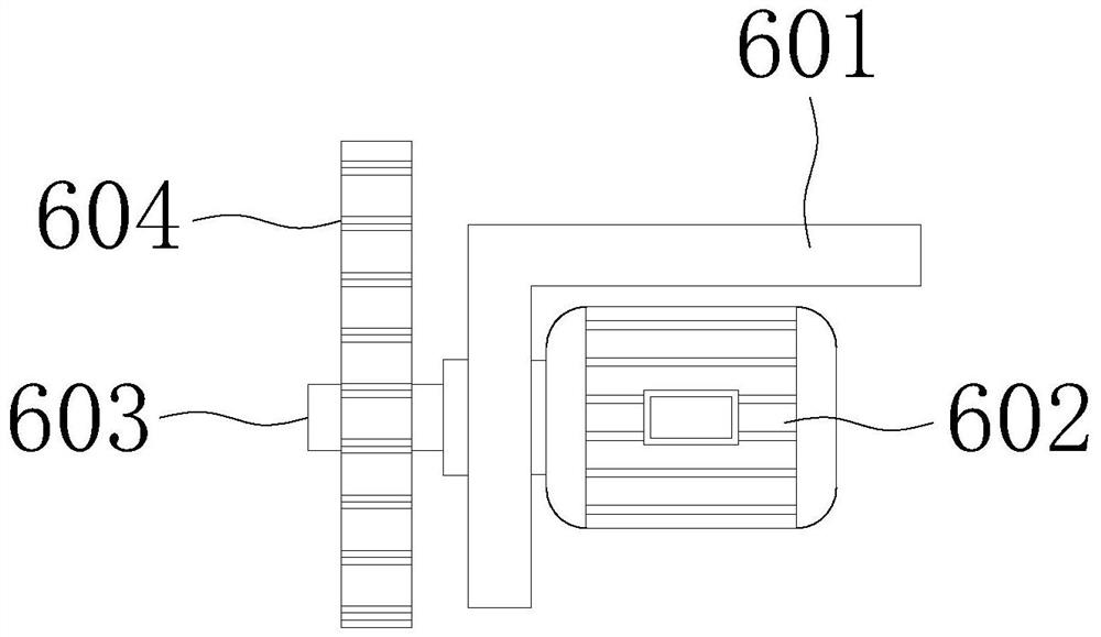
[0030] see Figure 1-7 , the present invention provides a technical solution: an adjustable intelligent processing equipment for jewelry inlay, including a work frame 1, a support mechanism 5, a lifting mechanism 6 and a control mechanism 8, and a chute is provided on one side of the work frame 1 2. Slider 3 is slidingly installed inside the chute 2, and processing plate 4 is fixedly installed on one side of the outer wall of slider 3. The supporting mechanism 5 is vertically arranged under the processing plate 4 in two groups, and the lifting mechanism 6 is installed horizontally. On one side of the work frame 1, the lifting mechanism 6 can drive the slider 3 and the processing plate 4 to move longitudinally relative to the work frame 1, and the control mechanism 8 includes an adjustment assembly and a conversion assembly, and the adjustment assembly can drive the conversion assembly to move laterally.

Embodiment 2

[0032] see Figure 1-7 , on the basis of Embodiment 1, the support mechanism 5 includes a sleeve 501, a lifting column 502, a spring 503 and a limit block 504, the sleeve 501 is fixedly installed on the inner top of the work frame 1, and the lifting column 502 is fixedly installed on the processing plate 4, the top of the sleeve 501 has an opening, one end of the lifting column 502 extends to the inside of the sleeve 501, one end of the spring 503 is fixed on the inner top of the sleeve 501, and the limit block 504 is fixed on the lifting column 502 The bottom end of the spring 503 is fixedly connected with the bottom of the limit block 504, and the processing plate 4 is supported and damped. On the one hand, the processing plate 4 can be supported and limited to ensure the stability of the processing plate 4. On the other hand, it can play a role of shock absorption in the lifting process of the processing plate 4, increasing the practicability of the processing equipment.

...


PUM


Abstract

The invention discloses adjustable intelligent processing equipment for jewelry inlaying, and relates to the technical field of jewelry processing equipment. The adjustable intelligent machining equipment for jewelry inlaying comprises a working frame, a supporting mechanism, a lifting mechanism and a regulating and controlling mechanism, a sliding groove is formed in the outer wall of one side of the working frame, a sliding block is slidably installed in the sliding groove, and a machining plate is fixedly installed on the outer wall of one side of the sliding block. According to the adjustable intelligent machining equipment for jewelry inlaying, jewelry can be conveniently fixed, positioning and fixing of the jewelry can be adjusted according to the size of the jewelry, meanwhile, fixing clamps can be converted according to the shape of the jewelry, on one hand, the fixing effect of the jewelry is improved, and the equipment ensures that no sliding phenomenon appears during jewelry processing; and on the other hand, the application range and the adjustability of the jewelry processing equipment are improved, so that the practicability of the jewelry processing equipment is improved, and the jewelry processing equipment is convenient to popularize and use.

Description

technical field [0001] The invention relates to the technical field of jewelry processing equipment, in particular to an adjustable intelligent processing equipment for inlaying jewelry. Background technique [0002] Jewelry raw materials generally include gold, silver, diamonds, gemstones, pearls, etc. When jewelry is processed and produced, gemstones need to be inlaid on the jewelry, so it is necessary to fix the jewelry, such as the patent with the publication number CN206603353U, which mainly includes By turning the rotating ring, the jewelry can be clamped by the clamping block, but this method has poor clamping effect, and the clamping block cannot be converted according to the shape of the jewelry, which will easily cause the jewelry to slide and affect the inlay of the jewelry Effect, not easy to promote and use. Contents of the invention [0003] The purpose of the present invention is to at least solve one of the technical problems in the prior art, and provide ...

Claims


Application Information

Patent Timeline
IPC IPC(8): A44C17/04
CPCA44C17/043A44C17/04
Inventor 曾智远
Owner 深圳市冠泰珠宝有限公司
Learn More