
Filter press with movable check valve and use method of filter press

A mobile, filter press technology, applied in separation methods, chemical instruments and methods, fixed filter element filters, etc., can solve the problems of low filter press efficiency and effect, filter cake reprocessing, clogging, etc. Achieve the effect of saving manpower and material resources, good sealing performance and simple operation

Inactive Publication Date: 2021-10-01
盛金平
View PDF0 Cites 1 Cited by
  • Summary
  • Abstract
  • Description
  • Claims
  • Application Information

AI Technical Summary

Problems solved by technology

[0006] The purpose of the present invention is to overcome the defects and deficiencies of the prior art, and provide a filter press with a movable non-stop valve to solve the problem of low efficiency and effect of the existing filter press, as well as the existence of sticky plates, Problems such as clogging, the need to equip a high-power feed pump, and the need to reprocess the filter cake, etc.

Method used


Image

  • Filter press with movable check valve and use method of filter press
  • Filter press with movable check valve and use method of filter press
  • Filter press with movable check valve and use method of filter press

Examples


Embodiment 1

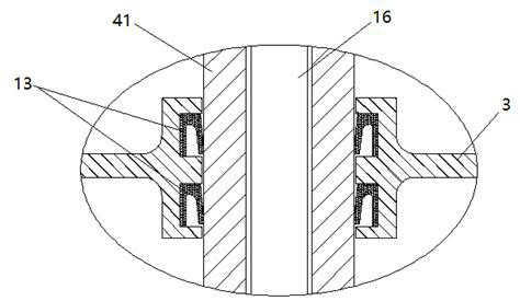
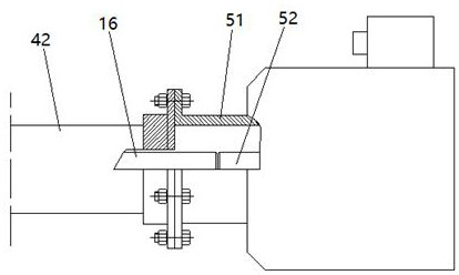
[0041] See Figure 1-8 A filter machine with a moving stop valve, including the cylinder 1, the front end of the cylinder 1, and fixedly connected to the pressing chamber 2 with which the cylinder 1 is fixedly connected to the sealing cover. 3, the rear of the cylinder 1 is provided with a reciprocating propulsion device 4 and a spool of the core driver 5, and the cylinder 1, respectively, the side walls of the rear end are respectively provided with a concentrated slurry inlet 6 and the filler outlet 7, a thick paste inlet 6 and the filtrate The outlet 7 corresponds to the feed valve 8 and the discharge valve 9; the inside of the cylinder 1 is slidably mounted, and the stop valve 10 includes a valve body 101 and passage of movable before and after the inner wall of the cylinder 1. The spool 102 of the inner flow channel of the valve body 101 is attached to the front end of the valve body 101, and the reciprocating propulsion device 4 drives the valve body 101 to move before and af...

Embodiment 2

[0061] See Figure 9 , 10 In this embodiment, the valve body 101 is a cylindrical structure, and the push rod connecting bracket 15 is also a cylindrical structure, and the outer diameter of the valve body 101 and the push rod connecting bracket 15 is slightly smaller than the inner diameter of the cylinder 1, and pushes the rod connection. The inner diameter of the front port of the bracket 15 is smaller than the inner diameter of the port of the valve body 101, thereby forming a valve seat stop structure at the front port of the push rod connection bracket 15; in addition, the rear end of the push rod connection bracket 15 is a hollow structure.

[0062] The spool 102 is located inside the valve body 101, and the spool 102 moves forward or backward on the drive of the spool driver 5. When moving backward, the spool 102 is pressed outside the front port of the propeller connection bracket 15. The end face (the valve seat stop is at the interior flow channel of the cutoff valve bod...

Embodiment 3

[0065] See Figure 11 , 12In this embodiment, the structure of the elastic damper 12 'is different from the elastic damper 12 structure in the first embodiment, which includes a throat 121' with a front end of the compression chamber 2 and can be sealed in the throat 121. The top of the front port of the front port is fixed to the outer wall of the L-shaped bracket 123 ', the vertical portion of the L-shaped bracket 123', the L-shaped bracket 123 ', and the horizontal tube 124' It is provided with the horizontal axis 125 ', the lateral axis 125', and the lateral axis 125 'can be passed before and after, respectively, and the passage of the rear end is respectively, and the horizontal axis 125' is located at the horizontal tube 124. The exterior of the part of the part is inherently inherently spring seat 126 'and the outer portion of the rosk 127', the outer spring seat 126 'and the spring seat 127' is set with a spring 128 '. In the through hole of the rear end of the transverse t...


PUM


Abstract

The invention discloses a filter press with a movable check valve and a use method of the filter press. The equipment comprises a cylinder body, a compaction chamber, a reciprocating propelling device and a valve element driver, an on-off valve is mounted in the cylinder body in a sliding manner and comprises a valve body capable of moving back and forth along the inner wall of the cylinder body and a valve core for opening and closing an internal flow channel of the valve body; a detachable filter plate is mounted at the front end of the valve body; the reciprocating propelling device drives the valve body to move back and forth along the inner wall of the cylinder body, and the valve element driver drives the valve element to open or close an internal flow channel of the valve body; the front end of the compaction chamber is provided with an elastic damper capable of blocking the front port of the compaction chamber. According to the invention, the configuration of a high-power feeding pump is omitted, and the investment and operation and maintenance costs are effectively reduced. According to the equipment, the filter pressing efficiency and effect are greatly improved, the filter plate is reversely washed, blockage is automatically cleaned, and the service life of the filter plate is prolonged; therefore, the solid-to-liquid ratio of the filter cake is guaranteed, retreatment of the filter cake is avoided, and the transportation cost of the filter cake is reduced.

Description

Technical field [0001] The present invention relates to the technical field for solid-liquid separation, and is specifically a filter machine with a moving stop valve and a method of use. Background technique [0002] The filter machine utilizes a special filter medium to apply a certain pressure to the subject, so that a mechanical apparatus for seizing liquid is a commonly used solid-liquid separation device. [0003] When the existing filter machine is filtered, the material (slurry) is injected into the filter chamber of the filtered plate, and the particles in the filter cloth or other filter medium mounted on the filter plate, so that it remains in filtered. The room, and the filtrate is discharged from the liquid elbow, thereby forming a filter cake in the filter chamber, and then pulling the filter plate by the filter machine, so that the filter cake is automatically falling to remove the filter cake to achieve the purpose of filtration. . [0004] Since the filter cake o...

Claims


Application Information

Patent Timeline
Patent Type & Authority Applications(China)
IPC IPC(8): B01D29/01B01D29/60B01D29/66B01D29/92B01D29/94
CPCB01D29/01B01D29/92B01D29/94B01D29/606B01D29/66
Inventor 盛金平
Owner 盛金平
Learn More