
button

A key and keycap technology, applied in electrical components, emergency actuators, electrical switches, etc., can solve the problems of inability to contact at the same time, the keycap pressing and recovery are not stable, and achieve the effect of reducing space

Active Publication Date: 2018-08-31
DARFON ELECTRONICS (SUZHOU) CO LTD +1
View PDF5 Cites 0 Cited by
  • Summary
  • Abstract
  • Description
  • Claims
  • Application Information

AI Technical Summary

Problems solved by technology

Yet the key cap of the specific multiple key of known keyboard (for example input key (Enter)) except the design of main cap body, has the design of the extension cap body that extends in main cap body otherwise, because extension cap body is formed by main cap body The edge of the body extends out, so the lifting and supporting mechanism of the known button cannot abut against the main cap body and the extension cap body extending from the main cap body at the same time, so the lifting and supporting mechanism of the known button cannot be pressed between the keycap and the keycap. During the recovery process, the main cap body and the extension cap body are supported, resulting in instability in the keycap pressing and recovery process

Method used


Image

  • button
  • button
  • button

Examples


Embodiment Construction

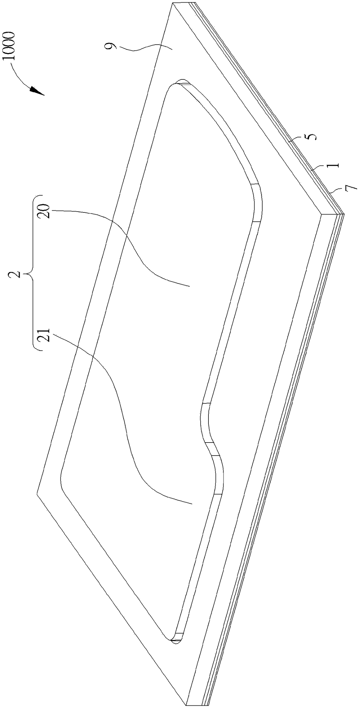
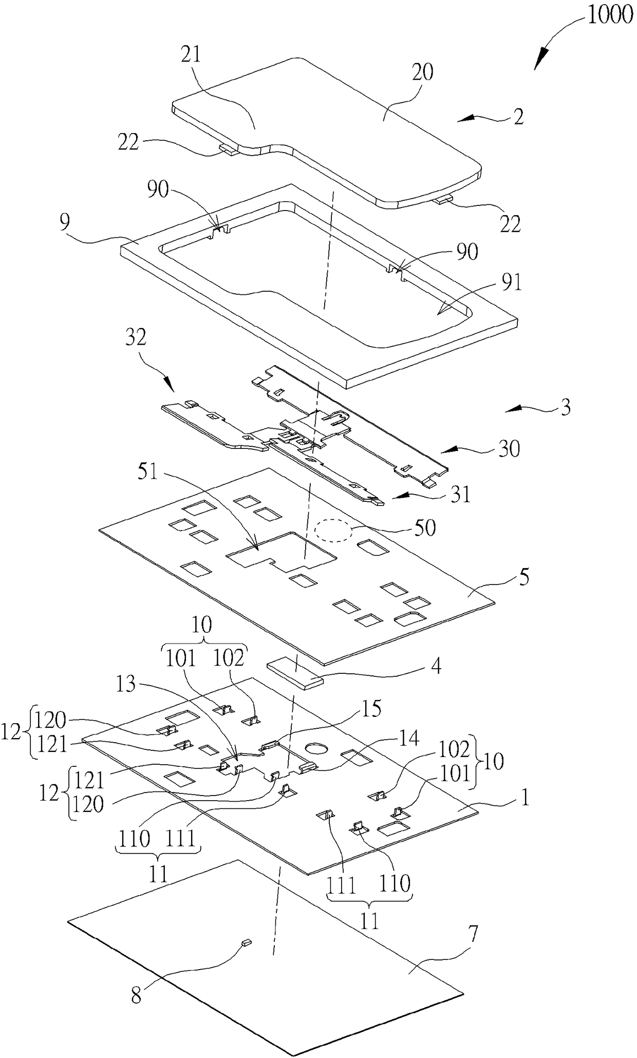
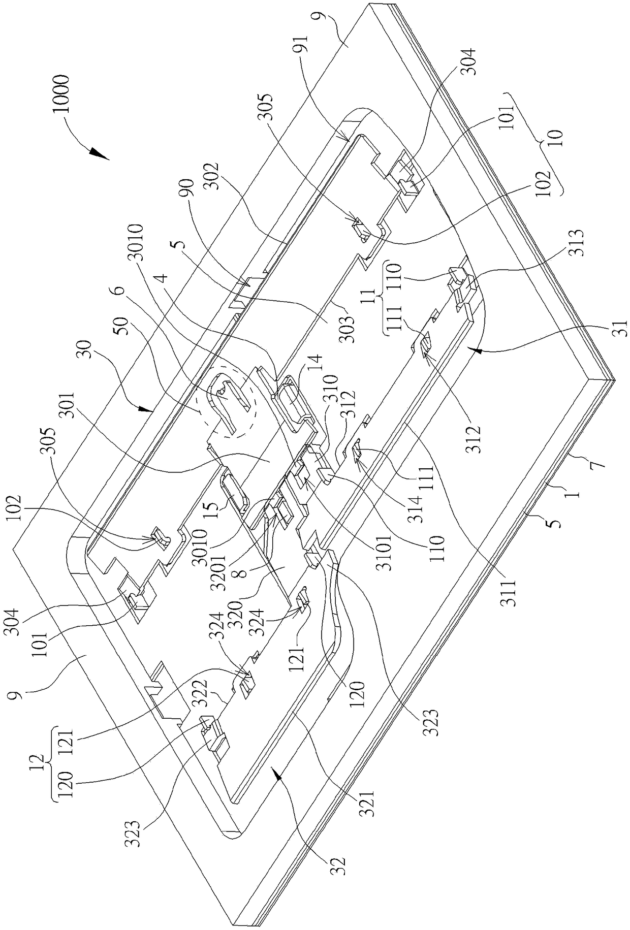
[0032] The directional terms mentioned in the following embodiments, such as: up, down, left, right, front or back, etc., are only directions referring to the attached drawings. Accordingly, the directional terms are used to illustrate and not to limit the invention. see Figure 1 to Figure 3 , figure 1 It is a schematic diagram of the appearance of a button 1000 according to an embodiment of the present invention, figure 2 It is a schematic diagram of the explosion of the button 1000 according to the embodiment of the present invention, image 3 It is a schematic diagram of the internal mechanism of the button 1000 according to the embodiment of the present invention. Such as Figure 1 to Figure 3 As shown, the button 1000 includes a bottom plate 1, a keycap 2, a support mechanism 3, a magnetic element 4, a first circuit board 5, a trigger arm 6, a second circuit board 7, a light emitting element 8 and a frame 9, and the keycap 2 is arranged on Above the base plate 1, t...


PUM


Abstract

A press button comprises a base board, a button cap, a supporting mechanism and a magnet component. The button cap is provided with a main cap body and an extended cap body which extends from the main cap body. The supporting mechanism comprises a first supporting member, a second supporting member and a third supporting member. The first supporting member and the second supporting member are pivoted with the base board and are connected with two opposite sides of the main cap body. The third supporting member is pivoted with the base board and is connected with the extended cap body. The first supporting member and the second supporting member are interlocked with the third supporting member. The magnet component is arranged on the base board and attracts at least one selected from the first supporting member, the second supporting member and the third supporting member so that the supporting mechanism drives the button cap to reset.

Description

technical field [0001] The present invention relates to a key, in particular to a key using magnetic attraction force as the driving force required for key cap reset. Background technique [0002] As far as current personal computer usage habits are concerned, the keyboard is one of the indispensable input devices for inputting characters, symbols or numbers. Not only that, all the consumer electronic products in daily life or the large-scale processing equipment used in the industry need to be equipped with keys as input devices to operate the above-mentioned electronic products and processing equipment. Generally speaking, in conventional keys, a rubber dome is disposed between the keycap and the bottom plate, so that when the keycap is pressed by the user, the dome rubber can drive the keycap to reset. However, the above-mentioned elastic member will cause the key to require a large height space, which is not conducive to the application of thinning the keyboard. [000...

Claims


Application Information

Patent Timeline
Patent Type & Authority Patents(China)
IPC IPC(8): H01H13/14H01H13/83
CPCH01H13/14H01H13/83H01H2221/04H01H2231/002
Inventor 许建士
Owner DARFON ELECTRONICS (SUZHOU) CO LTD
Learn More