
Integrated lipstick tube preparation mold and preparation process thereof

A lipstick tube and integrated technology, which is applied in the field of an integrated lipstick tube preparation mold and its preparation process, can solve the problems of complex demolding structure, inconvenient operation, inability to realize temperature control, etc., and achieves simple demolding structure and high automation level. Effect

Pending Publication Date: 2021-10-01
ANHUI YIXUAN METAL SCI & TECH CO LTD
View PDF12 Cites 0 Cited by
  • Summary
  • Abstract
  • Description
  • Claims
  • Application Information

AI Technical Summary

Problems solved by technology

[0004] The above-mentioned lipstick injection mold that is easy to remove the material still has some disadvantages, such as: the demoulding structure is complicated, the temperature control cannot be realized, and manual operation is required when blanking, which is inconvenient to operate

Method used


Image

  • Integrated lipstick tube preparation mold and preparation process thereof
  • Integrated lipstick tube preparation mold and preparation process thereof
  • Integrated lipstick tube preparation mold and preparation process thereof

Examples


Embodiment 1

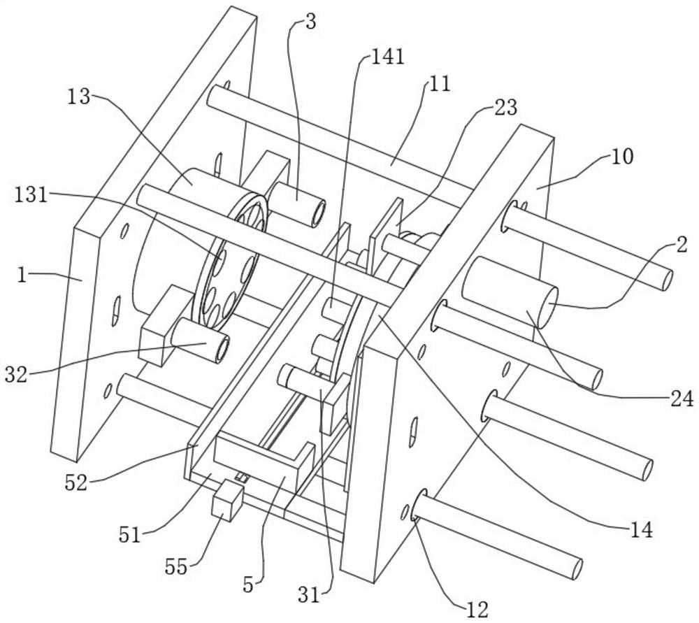
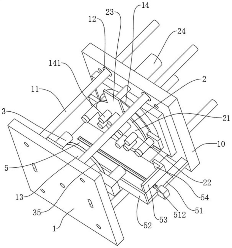
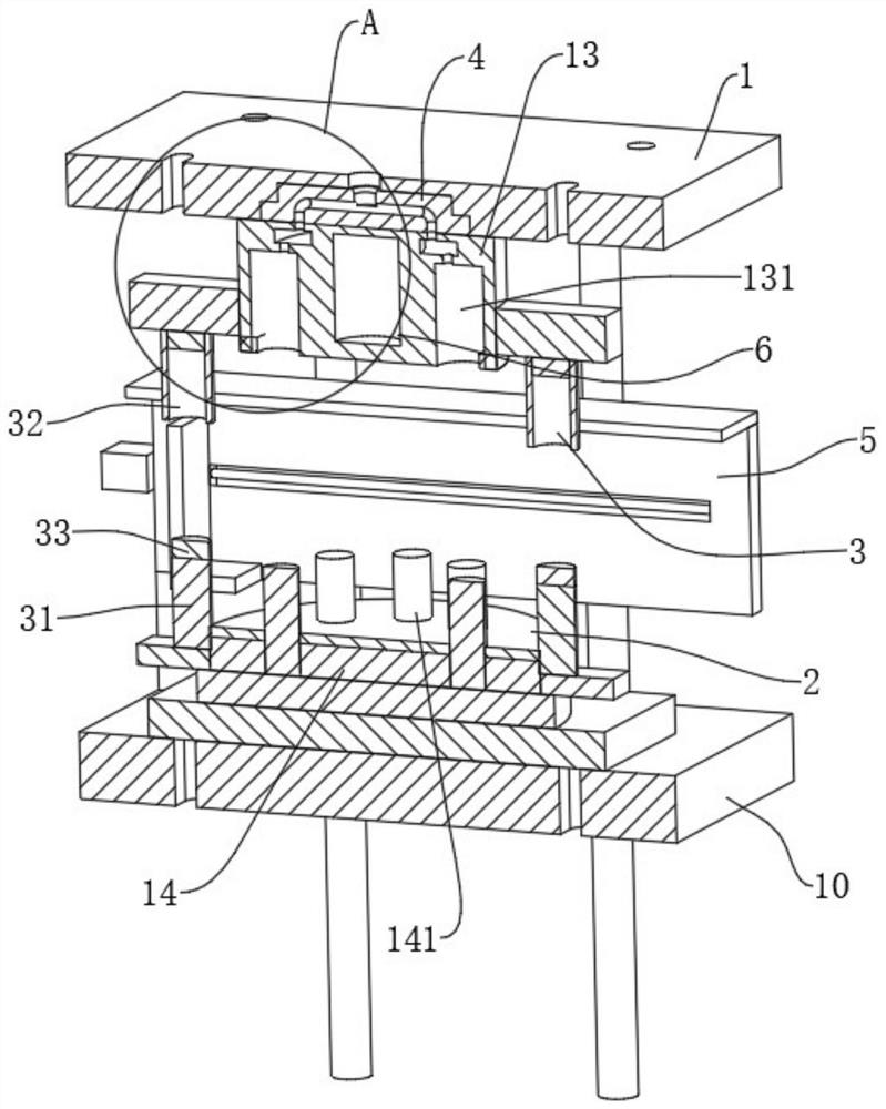
[0045] refer to figure 1 , figure 2 with image 3 One integrated port red tube is prepared, including the fixed-end of the fixed end in the injection molding machine and the movable die 10 mounted in the injection molding machine, where the fixed mold seat 1 is fixed to the side of the moving die 10 Several guides 11 in which the movable sleeve 12 is fixed to each other with the guide bar 11, which can provide the direction of the mold using the guide bar 11 and the guide sleeve 12; wherein the mold further includes the following portions: The fixed template 13 is mounted in the plane of the module 1, and a plurality of concave die cavities 131 for molding the red tube are fixed in the fixed template 13; mounted in the moving module 10 The template 14, and the movable die 141 is fixed to the dielectric core rod 141 for inserting the concave die cavity 131; a demolding assist of the exterior molding of the external molded core rod 141 is disposed on the moving template 14. Structure...

Embodiment 2

[0054] Unlike Example 1, the present embodiment also provides a preparation process of a molded plug-in manufacture, including the following steps:

[0055] S1, select T12 steel wire cutting and polishing manufacturing the exit molding 1 and the moving form 10, select the CR12MOV steel wire cutting and polishing the application of the model plate 13 and the moving template 14;

[0056] S2, the template 13 and the moving template 14 are larper, quenching and tempering heat treatment, after which the secondary grinding, wherein the isothermal ballification process is: heating in 860-890 ° C for 2 h, cooling to 740-760 ° C Isothermal 4h, the furnace is cold to 500 ° C, the quenching and tempering process are: heating temperature 1020-1050 ° C, oil cold or air cooling, control hardness 54-58 HRC, after 530-560 ° C for tempering.

[0057] S3, assemble the insert 41 to the fixed die 1;

[0058] S4, the template 13 is assembled to the fixed die 1, and the movable template 14 is assembled...


PUM


Abstract

The invention discloses an integrated lipstick tube preparation mold and a preparation process thereof. The integrated lipstick tube preparation mold is characterized by comprising a fixed mold base installed at a fixed end in an injection molding machine and a movable mold base installed at a movable end in the injection molding machine and further comprising a fixed mold plate, a movable mold plate, a demolding auxiliary structure and a locking structure, wherein the fixed mold plate is installed on the face, close to the movable mold base, of the fixed mold base, a plurality of concave mold cavities for molding lipstick tubes are fixed in the fixed mold plate, the movable mold plate is mounted on one face, close to the fixed mold base, of the movable mold base, a plurality of mold core rods used for being inserted into the concave mold cavities are fixed on the movable mold plate, the demolding auxiliary structure is arranged on the movable mold plate and used for assisting in demolding of the lipstick tubes formed outside the mold core rods, and the locking structure is used for sealing the movable mold plate and the fixed mold plate when the movable mold plate and the fixed mold plate are closed. The integrated lipstick tube preparation mold has the advantages that the demolding structure is simple, temperature control can be achieved, manual operation is not needed during blanking, and the automation level is high.

Description

Technical field [0001] The present invention relates to the field of lipstick production, and more particularly to a one-piece port red tube preparation mold and a preparation process thereof. Background technique [0002] At present, there are many red tubes for plastic materials. It is widely used in the production of injection molding processes during production, and the lipstur tubes that are injection molded can be formed. [0003] The existing bulletin is a Chinese patent of CN209381313U, which discloses a convenient desorrential lipstick injection mold, including a mounting tube, and a joint pipe in the mounting pipe. The inside of the mounting pipe is mounted, and the silicone mold is fitted. An connection between the connecting tube, the connecting pipe and the mounting tube is provided with a plurality of sets of vent holes in the outer wall of the connecting tube near the end of the silicone mold, and the vent hole is disposed along the outer wall of the connecting pip...

Claims


Application Information

Patent Timeline
IPC IPC(8): B29C45/26B29C45/40B29C45/64B23P15/24
CPCB29C45/2602B29C45/261B29C45/4005B29C45/64B23P15/24B29C2045/2683B29C2045/645
Inventor 陈靖陈文俊陈文胜陈琦
Owner ANHUI YIXUAN METAL SCI & TECH CO LTD
Learn More