Automatic sand loading equipment

A technology for loading sand and equipment, applied in the directions of packaging, transportation packaging, transportation and packaging, etc., can solve the problem of needing labor for pockets, and achieve the effect of reducing operability and increasing production.

Pending Publication Date: 2021-10-01
付国永
View PDF8 Cites 0 Cited by
  • Summary
  • Abstract
  • Description
  • Claims
  • Application Information

AI Technical Summary

Problems solved by technology

But at the same time of loading, there is a problem that bagging needs manual work.

Method used


Image

  • Automatic sand loading equipment
  • Automatic sand loading equipment
  • Automatic sand loading equipment

Examples


specific Embodiment approach 1

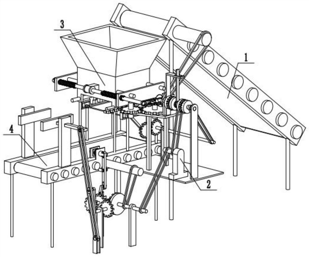
[0029] Combine below Figure 1-13 Describe this embodiment, an automatic sand loading equipment, including a feeding assembly 1, a bagging assembly 2, a bagging device 3, and a sealing device 4, the feeding assembly 1 is connected to the bagging device 3, and the bagging assembly 2 is connected to the bagging device The bagging device 3 is connected, the bagging assembly 2 is connected with the sealing device 4 , and the bagging device 3 is connected with the sealing device 4 .

specific Embodiment approach 2

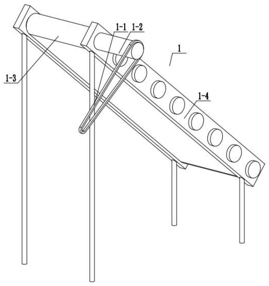
[0030] Combine below Figure 1-13 Describe this embodiment, this embodiment will further explain the first embodiment, the feeding assembly 1 includes a transmission belt 1-1, a roller 1-2, a conveyor belt 1-3, a feeding bracket 1-4, a transmission belt 1-1- 1 is connected with the roller one 1-2, the roller one 1-2 is connected with the conveyor belt one 1-3, and the roller one 1-2 is rotatably connected with the feeding bracket 1-4.

specific Embodiment approach 3

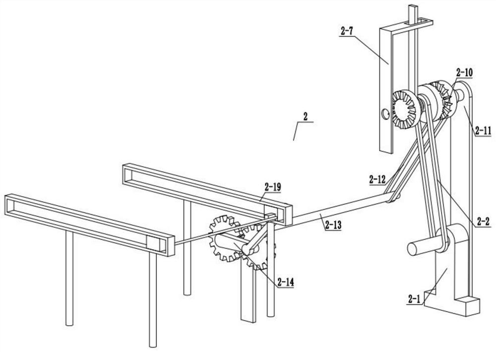
[0031] Combine below Figure 1-13 Describe this embodiment, this embodiment will further explain Embodiment 1. The bagging assembly 2 includes a motor 2-1, a transmission belt 2-2, a cross rod bearing 2-3, a cross rod 2-4, and a limit block 1 2-5, control rod 2-6, control rod bracket 2-7, clutch one 2-8, clutch two 2-9, clutch three 2-10, clutch bracket 2-11, transmission belt three 2-12, spur shaft One 2-13, rotating arm one 2-14, spur gear support one 2-15, spur gear one 2-16, connecting rod 2-17, bagging block 2-18, fixed chute 2-19, fixed rod One 2-20, the motor 2-1 is connected with the transmission belt two 2-2, the transmission belt two 2-2 is connected with the cross rod bearing 2-3, the cross rod bearing 2-3 is fixedly connected with the cross rod 2-4, and the limit Block one 2-5 is fixedly connected with cross rod 2-4, limit block one 2-5 is rotationally connected with control rod 2-6, control rod 2-6 is slidingly connected with control rod bracket 2-7, clutch one 2...


PUM


Abstract

The invention relates to the field of loading machinery, in particular to automatic sand loading equipment. The automatic sand loading equipment is characterized in that fine sand needing to be loaded is conveyed through a feeding assembly; a bagging assembly fixes a gunny bag to a bagging device; a cross rod is driven through a cross rod bearing; a clutch is meshed with a spur gear I to drive the spur gear I through sliding of a control rod; a bagging block is used for loading the gunny bag; the bagging device is used for expanding the opening of the gunny bag to load fine sand; a screw rod drives a fixed plate and driven gear shafts drive a rack through engagement of a clutch, so that the bag is expanded, the sealing device is used for sealing the loaded gunny bag; a rotating rod I is driven through a trigger block; and then the sliding block I drives a spur gear II to be meshed with an end face gear shaft and drives a spur gear III to be meshed with a spur gear shaft III, so that a sealing plate slides. Through adoption of the automatic sand loading equipment, loading of the gunny bag is added on the basis of sand loading, operability of workers is reduced, and meanwhile the sand loading yield is increased.

Description

technical field [0001] The invention relates to the field of charging machinery, in particular to an automatic sand loading device. Background technique [0002] For some materials that need to be bagged with fine particles such as sand, mud, and soil materials, most of them use manual labor to carry out the bagging operation, which is time-consuming, laborious and inefficient, which is not conducive to improving production and operation efficiency. It is also not conducive to quickly respond to the bagging requirements of these materials. For example, the patent number is CN201920161887.0, an automatic bagging machine, which is characterized in that: it includes a loader and multiple sandbags, and the front end of the loader is equipped with a sand pushing bucket. , the rear end of the sand-loading push bucket is connected to the front end of the loader, and a plurality of sandbag-loading through holes are arranged and distributed on the sand-loading push bucket. The raise...

Claims


Application Information

Patent Timeline
IPC IPC(8): B65B43/54B65B43/52B65B43/26B65B1/06B65B51/08B65B37/00
CPCB65B43/54B65B43/52B65B43/26B65B1/06B65B51/08B65B37/005
Inventor 付国永
Owner 付国永
Why Eureka
Try Eureka