Automatic packaging equipment for textile printing and dyeing

A textile printing and dyeing and automatic technology, which is applied in the field of textile printing and dyeing, can solve the problems of lack of automatic packaging devices, etc., and achieve the effect of reducing operability and fluidity

Inactive Publication Date: 2021-06-29
邢海东
View PDF0 Cites 0 Cited by
  • Summary
  • Abstract
  • Description
  • Claims
  • Application Information

AI Technical Summary

Problems solved by technology

[0002] Nowadays, the printing and dyeing machinery and equipment used in printing and dyeing factories lack automatic packaging devices. After printing and dyeing fabrics, they need to be packaged again before they can be sold.

Method used


Image

  • Automatic packaging equipment for textile printing and dyeing
  • Automatic packaging equipment for textile printing and dyeing
  • Automatic packaging equipment for textile printing and dyeing

Examples


specific Embodiment approach 1

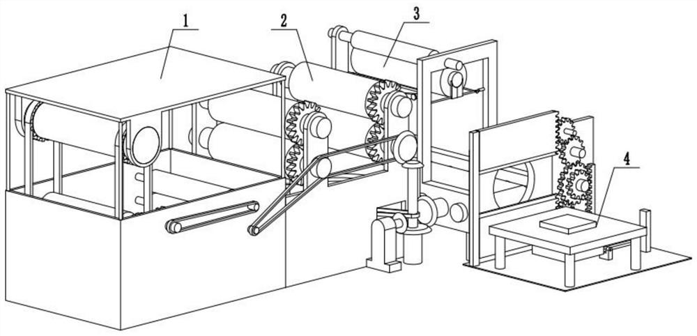
[0039] Combine below Figure 1-22 Describe this embodiment, an automatic packaging equipment for textile printing and dyeing, including a printing and dyeing assembly 1, a drying assembly 2, a loading assembly 3, and a packaging assembly 4, the printing and dyeing assembly 1 is connected to the drying assembly 2, and the drying assembly 2 is connected to the loading assembly 3-phase connection.

specific Embodiment approach 2

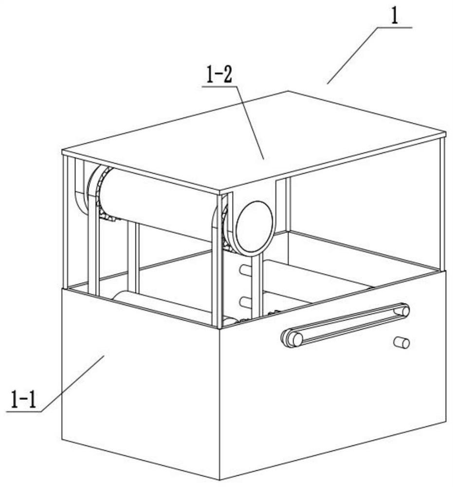
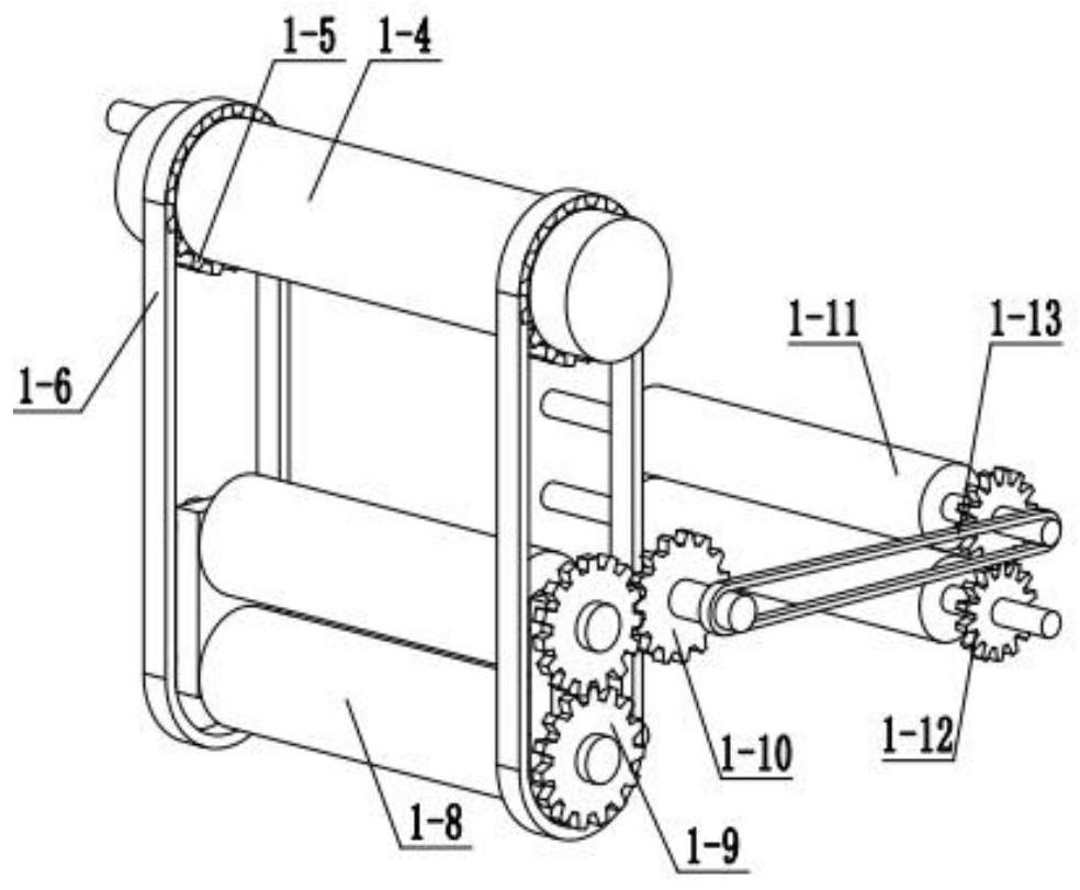
[0041] Combine below Figure 1-22 Describe this embodiment, this embodiment will further explain Embodiment 1, the printing and dyeing assembly 1 includes a printing and dyeing box 1-1, a printing and dyeing box fixing bracket 1-2, a rotating armrest 1-3, a roller 1-4, and a gear 1 -5, chain 1-6, fixed block 1-7, printing and dyeing rod one 1-8, gear group one 1-9, gear shaft one 1-10, printing and dyeing rod two 1-11, gear group two 1-12, transmission belt One 1-13, the printing and dyeing box 1-1 is fixedly connected with the printing and dyeing box fixing bracket 1-2, the rotating handrail 1-3 is fixedly connected with the roller one 1-4, and the roller one 1-4 is fixedly connected with the printing and dyeing box fixing bracket 1-2 Rotation connection, roller 1-4 is fixedly connected with gear 1-5, gear 1-5 is meshed with chain 1-6, chain 1-6 is fixedly connected with fixed block 1-7, fixed block 1-7 is connected with printing and dyeing rod One 1-8 is rotationally connec...

specific Embodiment approach 3

[0044] Combine below Figure 1-22 Describe this embodiment, this embodiment will further explain Embodiment 1, the drying assembly 2 includes a drying box 2-1, a drying rod 2-2, a gear set 3 2-3, a drying rod 2 2- 4. Gear group four 2-5, transmission belt two 2-6, bevel gear one 2-7, fan sleeve 2-8, fan shaft 2-9, fan blade 2-10, drying box 2-1 and drying Rod one 2-2 is rotationally connected, drying rod one 2-2 is fixedly connected with gear set three 2-3, drying rod two 2-4 is rotationally connected with drying box 2-1, drying rod two 2-4 is connected with Gear group 4 2-5 is fixedly connected, transmission belt 2 2-6 is connected with printing and dyeing rod 2 1-11, transmission belt 2 2-6 is connected with drying rod 1 2-2, transmission belt 2 2-6 is connected with drying rod 2 2-4 fit connection, bevel gear 1 2-7 is fixedly connected with drying rod 2 2-4, fan sleeve 2-8 is fixedly connected with drying box 2-1, fan sleeve 2-8 is connected with fan shaft 2- 9 is rotatio...


PUM


Abstract

The invention relates to the field of textile printing and dyeing, in particular to automatic packaging equipment for textile printing and dyeing. A gear is meshed with a chain through rotation of a rotating handrail, then a fixing block drives a first printing and dyeing rod to slide up and down, cloth penetrates through the first printing and dyeing rod and then enters a second printing and dyeing rod, and the cloth enters a first drying rod after being dyed; the cloth is dried through rotation of fan blades, the dried cloth enters a rotating column, the cloth is wound around a packaging rod, the cloth makes contact with a trigger baffle, then a first rotating rod rotates to drive a rack to slide, and then the cloth is cut through a blade; and the cut cloth enters a packaging table, and through sliding of a third sliding block, a third rotating rod rotates to drive an upper packaging sliding block and a lower packaging sliding block to package the cloth. According to the automatic packaging equipment, the cloth is cut off and packaged, so that the operability of a processing machine is reduced when the cloth is produced, and the mobility of the cloth during transportation is reduced through the packaging operation.

Description

technical field [0001] The invention relates to the field of textile printing and dyeing, in particular to an automatic packing device for textile printing and dyeing. Background technique [0002] Nowadays, the printing and dyeing machinery and equipment used in printing and dyeing factories lack automatic packaging devices. After printing and dyeing fabrics, they need to be packaged again before they can be sold. Contents of the invention [0003] The purpose of the present invention is to provide a kind of textile printing and dyeing automatic packaging equipment, which can dye the cloth through printing and dyeing components, drying components, loading components, packing components, printing and dyeing components, drying components to dry the dyed cloth, and loading components The cloth is loaded, and the packing component packs the loaded cloth. [0004] The purpose of the present invention is achieved through the following technical solutions: [0005] An automati...

Claims


Application Information

Patent Timeline
IPC IPC(8): D06B3/10D06H7/02D06B15/00B65B27/08F26B13/14F26B21/00
CPCB65B27/08D06B3/10D06B15/00D06H7/02F26B13/14F26B21/004
Inventor 邢海东
Owner 邢海东
Why Eureka
Try Eureka