Livestock feed stirring equipment with automatic feeding function

A feed mixing and automatic feeding technology, which is applied to mixers, feeds, and mixer accessories with a rotating mixing device, can solve problems such as clogging and reduce the effect of feed bearing, so as to prevent clogging, reduce operability, and enhance tightness. Effect

Pending Publication Date: 2021-08-10
汤欣情
View PDF0 Cites 0 Cited by
  • Summary
  • Abstract
  • Description
  • Claims
  • Application Information

AI Technical Summary

Problems solved by technology

[0004] Therefore, in order to solve the above-mentioned shortcomings of the sliding of the container and the blockage of the feed inlet by raw materials and the reduction of the feed carrying effect, the present invention provides a livestock feed mixing device with automatic feeding

Method used


Image

  • Livestock feed stirring equipment with automatic feeding function
  • Livestock feed stirring equipment with automatic feeding function
  • Livestock feed stirring equipment with automatic feeding function

Examples


Embodiment 1

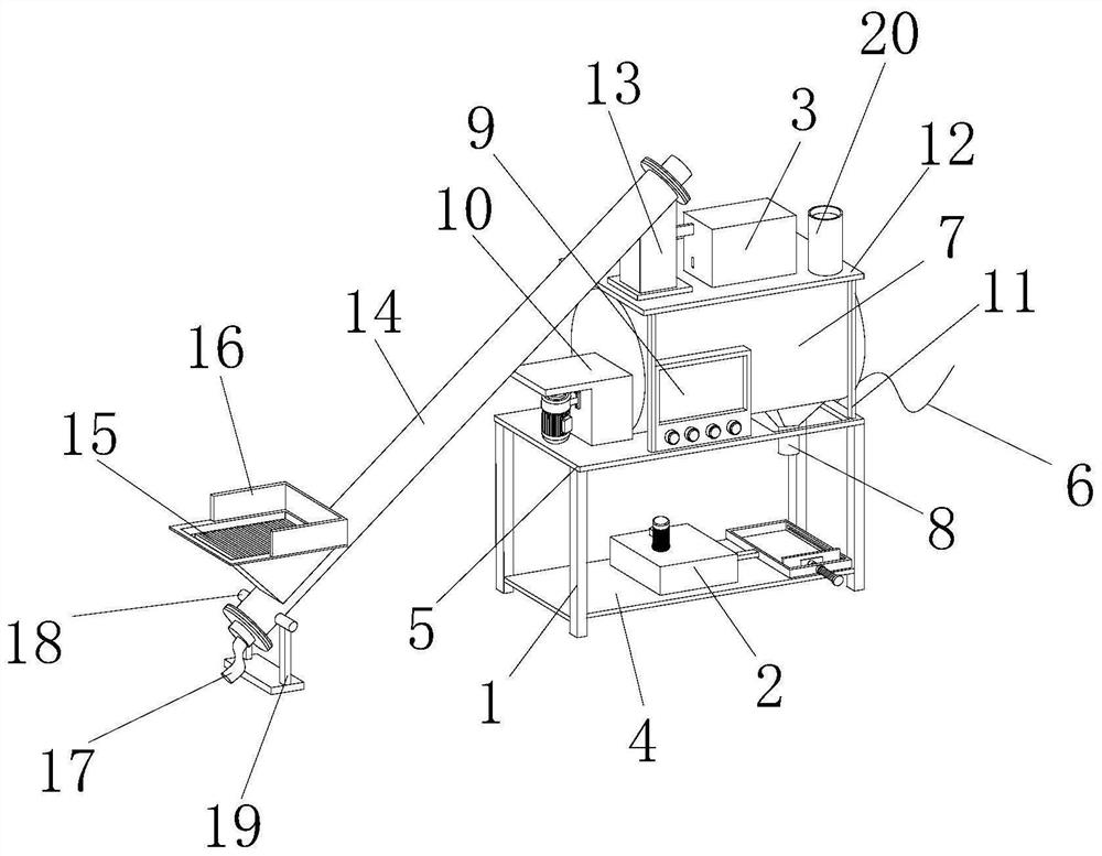
[0030] see figure 1 , the present invention provides a kind of livestock feed mixing equipment with automatic feeding through improvement, including a leg 1, the inner bottom of the leg 1 is fixed with the first workbench 4, and the top of the leg 1 is fixed with the second workbench 5 as a whole, The right side of the second workbench 5 is provided with a power cord 6, the middle part of the top of the second workbench 5 is vertically provided with a stirring tank 7, the right end of the bottom of the stirring tank 7 is connected with the discharge port 8, and the left end of the stirring tank 7 is vertically provided with a Control panel 9, mixing tank 7 left side is provided with stirring device 10, the top of second workbench 5 is fixed with support rod 11, and the top of support rod 11 is fixed with the 3rd workbench 12, and the left end of the 3rd workbench 12 top is connected with The middle part of the feed port 13 is connected, the top of the feed port 13 is fixed to ...

Embodiment 2

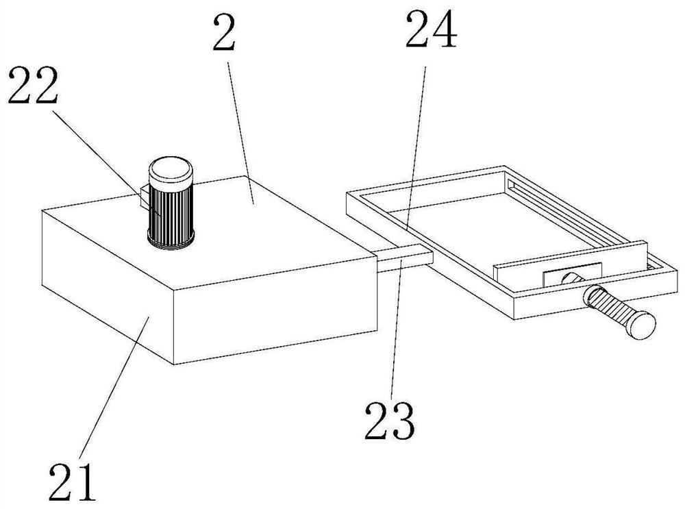
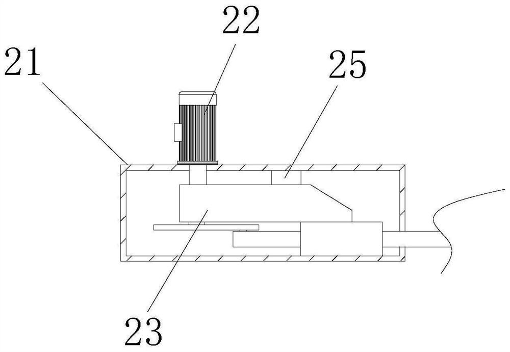
[0037] The present invention provides a kind of animal husbandry feed mixing equipment with automatic feeding through improvement. The first motor 22, the motor refers to an electromagnetic device that realizes electric energy conversion or transmission according to the law of electromagnetic induction, and the motor is used in the circuit. The letter M (the old standard uses D) indicates that its main function is to generate driving torque as a power source for electrical appliances or various machines. The generator is indicated by the letter G in the circuit. Its main function is to use mechanical energy to convert electrical energy.

[0038] The present invention provides a kind of animal husbandry feed mixing equipment with automatic feeding through improvement, and its working principle is as follows;

[0039] First, the user can place the supporting feet 1 and the bracket 19 horizontally on the place where they need to use, and then connect the power cord 6 arranged on ...


PUM

PropertyMeasurementUnit
Lengthaaaaaaaaaa
Thicknessaaaaaaaaaa

Abstract

The invention discloses livestock feed stirring equipment with an automatic feeding function, which comprises supporting feet, wherein an auxiliary mechanism is arranged at the right end of the top of a first workbench, and when a reciprocating device arranged in the auxiliary mechanism swings, a first ejector rod can drive a clamping device to swing, so that the tightness of feed bearing can be enhanced, and more feed can be contained. By means of arranging a clamping device on the right side of the first ejector rod and arranging a hand wheel in the clamping device, the operability of a user can be reduced, and the fixing effect of a feed bearing box is enhanced. The top of a third workbench is provided with an impacting device, when two second ejector rods in the impacting device slide in sliding grooves, and the two ejector rods can hit a feeding port respectively, so that the phenomenon that the feeding port is blocked can be prevented, and the blanking speed of raw materials is increased.

Description

technical field [0001] The invention relates to the related field of feed stirring, in particular to a livestock feed stirring equipment with automatic feeding. Background technique [0002] Animal husbandry refers to the use of livestock, poultry and other animals that have been artificially raised and domesticated by us, or the physiological functions of wild animals such as deer, musk deer, fox, mink, otter, quail, etc., through artificial breeding and breeding, so that they can use pasture and feed The process of converting plant energy into animal energy to obtain livestock products such as meat, eggs, milk, wool, cashmere, hides, silk, and medicinal materials is an extremely important link in the material exchange between humans and nature. Animal husbandry is an important part of agriculture. The components are listed as the two pillars of agricultural production together with the planting industry, and when feeding livestock, it is necessary to use feed for feeding, ...

Claims


Application Information

Patent Timeline
IPC IPC(8): B01F15/02A23N17/00B01F3/20B01F7/00B01F15/00B01F23/70
CPCA23N17/007B01F23/708B01F27/00B01F35/12B01F35/30B01F35/43B01F35/187B01F35/717B01F35/71775B01F35/754B01F35/7549B01F35/7547B01F35/79B01F2101/18
Inventor 汤欣情
Owner 汤欣情
Why Eureka
Try Eureka