Eureka AIR delivers breakthrough ideas for toughest innovation challenges, trusted by R&D personnel around the world.

Novel damper backpressure device

A technology of back pressure device and damper, which is applied in the textile field, can solve the problems of manufacturing precision requirements and high cost, complicated installation and adjustment process, complicated mechanical structure, etc., and achieve the effect of low noise and vibration frequency, light weight and simple operation

Pending Publication Date: 2021-10-01
SUZHOU IMAGIN MACHINERY
View PDF0 Cites 0 Cited by
  • Summary
  • Abstract
  • Description
  • Claims
  • Application Information

AI Technical Summary

Problems solved by technology

[0002] Generally speaking, the back pressure of loosening or winding machinery on the market basically relies on the principle of mechanical force arm balance (gravity balance) or the principle of spring tension and friction balance to achieve a certain resistance. Among them, the back pressure damping part The mechanical structure is complex, the manufacturing precision requirements and cost are high, and the stability is poor. The installation and adjustment process is relatively complicated, and the requirements for professional skills are relatively high. It is difficult for ordinary operators to perform quantitative adjustment of machinery (back pressure) without special training. And control, due to the differences in production, processing, assembly and debugging, it is difficult to keep the back pressure of each spindle consistent and constant

Method used


Image

  • Novel damper backpressure device
  • Novel damper backpressure device

Examples


Embodiment Construction

[0012] In order to make the technical solution of the present invention clearer, the present invention will be further described below in conjunction with specific embodiments of the accompanying drawings.

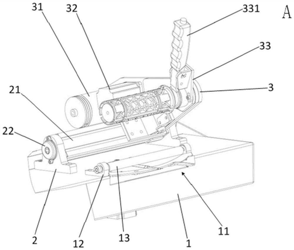
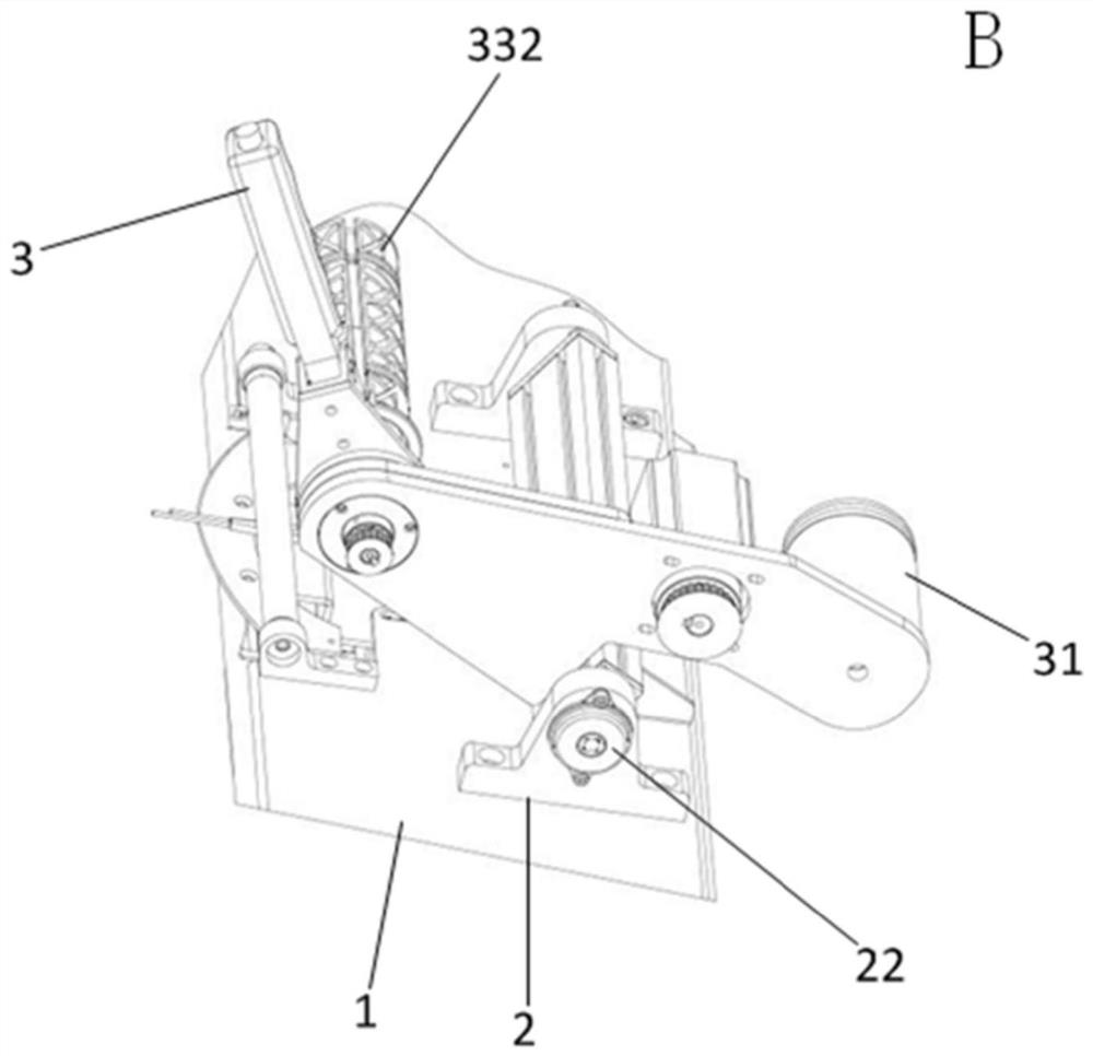
[0013] like Figure 1-2 As shown, a new type of damper back pressure device according to the embodiment of the present invention includes a workbench 1, and the workbench 1 is provided with an installation groove 11, and the two sides of the installation groove 11 are located symmetrically on the upper surface of the workbench 1. A driven shaft fixing block 12 is provided, and the driven shaft fixing block 12 is directly provided with a driven shaft 13. The upper surface of the workbench 1 is located at the rear of the installation groove 11 and is laterally symmetrically provided with a rotating shaft fixing block 2. The rotating shaft A rotating shaft 21 is arranged between the fixed blocks 2, and dampers 22 are arranged symmetrically at both ends of the rotating shaft 2...


PUM


Abstract

The invention discloses a novel damper backpressure device. The novel damper backpressure device comprises a working table, a mounting groove is formed in the working table, driven shaft fixing blocks are arranged on the two sides of the mounting groove, driven shafts are directly arranged on the driven shaft fixing blocks, rotating shaft fixing blocks are arranged on the upper surface of the working table, a rotating shaft is arranged between the rotating shaft fixing blocks, and dampers are symmetrically arranged at the two ends of the rotating shaft. The outer side surface of the rotating shaft is fixedly connected with a mounting plate, a motor is arranged in the middle of the inner side surface of the mounting plate, a weight tube is arranged on the side of the motor, a mounting frame is arranged on the side of the motor, and a handle and a bobbin mounting cylinder are arranged on the mounting frame and are perpendicular to each other. In the operation process of the novel damper backpressure device, a bobbin is fixedly installed on the bobbin mounting cylinder and makes contact with the driven shafts, the weight tube is arranged on the surface of the inner side of the mounting plate, the weight of the weight tube is increased, the weight tube and the weight of the bobbin are mutually balanced, and the situation that the overall weight of the bobbin acts on the driven shafts, and the operation quality is affected is prevented.

Description

technical field [0001] The invention relates to the technical field of textiles, in particular to a novel damper back pressure device. Background technique [0002] Generally speaking, the back pressure of loosening or winding machinery on the market basically relies on the principle of mechanical force arm balance (gravity balance) or the principle of spring tension and friction balance to achieve a certain resistance. Among them, the back pressure damping part The mechanical structure is complex, the manufacturing precision requirements and cost are high, and the stability is poor. The installation and adjustment process is relatively complicated, and the requirements for professional skills are relatively high. It is difficult for ordinary operators to perform quantitative adjustment of machinery (back pressure) without special training. And control, due to the differences in production, processing, assembly and debugging, it is difficult to keep the back pressure of each...

Claims


Application Information

Patent Timeline
Patent Type & Authority Applications(China)
IPC IPC(8): B65H59/04
CPCB65H59/04
Inventor 赵波姚卫康
Owner SUZHOU IMAGIN MACHINERY
Why Eureka
Eureka Blog
Learn More