
Portable electric detonator

An electric detonator, portable technology, applied in the field of portable electric detonators, can solve the problems of low production efficiency, inconvenient handling, unfavorable continuous production, etc., to improve production speed and production efficiency, simplify structure and assembly process , The effect of simplifying the assembly production process

Active Publication Date: 2021-10-01
北京凯米迈克科技有限公司
View PDF9 Cites 0 Cited by
  • Summary
  • Abstract
  • Description
  • Claims
  • Application Information

AI Technical Summary

Problems solved by technology

[0005] 1. The bayonet plug is processed at the end of the long leg line through injection molding. The injection molding process of the bayonet plug is complicated and the production efficiency is low.
[0006] 2. After the bayonet plug is injected at one end of the long-legged line, there are differences in the structure and state of the two ends of the long-legged line. During the packaging, storage and transportation process, they need to be treated separately, and the two ends cannot be mixed, which increases the difficulty and cost of packaging, storage and transportation.
[0007] 3. After the long leg line is directly processed and connected with the ignition element or the electronic control module through the core wire head reserved during the injection molding of the bayonet plug, the long leg line as a whole needs to passively follow the ignition element or electronic control module to transfer to the follow-up The processing process increases the additional logistics transfer volume and the processing difficulty of the next process with long foot lines
[0008] 4. There are many different meters and specifications of the long-legged wire itself. After the long-legged wire is directly processed and connected with the ignition element or the electronic control module through the wire core and head reserved during the injection molding of the bayonet plug, there is no difference in the original Due to the different lengths of the igniting elements, there are additionally a variety of specification distinctions, which require frequent specification changes during production, which is not conducive to continuous production, and increases additional classification management storage and transportation scheduling costs.
[0009] 5. During the integrated injection molding process of the bayonet plug and the long-legged wire, the high-temperature injection plastic of the bayonet plug will cause the insulation skin of the long-legged wire core to melt, which is easy to form short-circuit unqualified products, and the traditional bayonet plug is made of opaque material, and the card The processing quality inside the mouth plug cannot be checked and judged conveniently, which brings great inconvenience to subsequent processing
[0010] 6. In the traditional integrated structure of long leg line and bayonet plug, the length of the bayonet plug is relatively short, and the exposed length of the bayonet plug of the final electric detonator product is usually about 10mm. It is inconvenient to use and operate on site. Operators Had to handle the position of the base detonator shell, which increased the risk of operation safety and violated the intrinsic safety requirements
Utility model patent 202020193388.2 "A Reinforced Electronic Ignition Part and Its Electronic Detonator" discloses a structure of a fully assembled reinforced electronic igniter and its detonator. The technical problem of fast and convenient connection (bayonet plug) is not solved, and the current conventional assembly method of electric detonators is still used, which cannot meet the requirements of large production capacity, high output, and rapid assembly production.

Method used


Image

  • Portable electric detonator
  • Portable electric detonator
  • Portable electric detonator

Examples


Embodiment 1

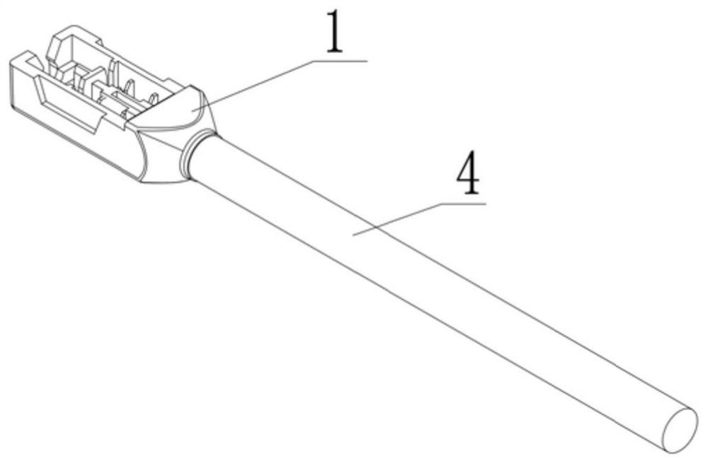
[0041] This embodiment provides a portable electric detonator, such as figure 1 As shown, it includes an insulated electrical connector 1, an electric ignition element 2 and a basic detonator 4.

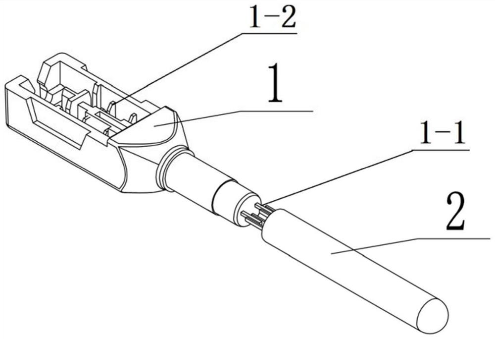
[0042] Such as figure 2As shown, the insulating connector 1 is a structure in which one end of the metal terminal is covered with an insulating elastic material as an electric detonator bayonet plug to realize the electrical connection with the relevant electronic devices and the mechanical connection with the extension parts. The other end of the insulating connector 1 Used as a junction box for extension connecting wires, the insulating connector 1 is an integrated structure composed of an electric detonator bayonet plug and a junction box. Both the electric detonator bayonet plug and the junction box housing are insulating materials, preferably plastic. The exposed metal terminal part of the bayonet plug of the electric detonator is used as the metal terminal 1-1, and the insula...

Embodiment 2

[0049] On the basis of Embodiment 1, the electric detonator further includes a reinforcing tube 3 .

[0050] The outer diameter of the small-diameter section of the electric-related detonator bayonet plug of the insulating connector 1 is consistent with the inner diameter of the reinforcing tube 3 .

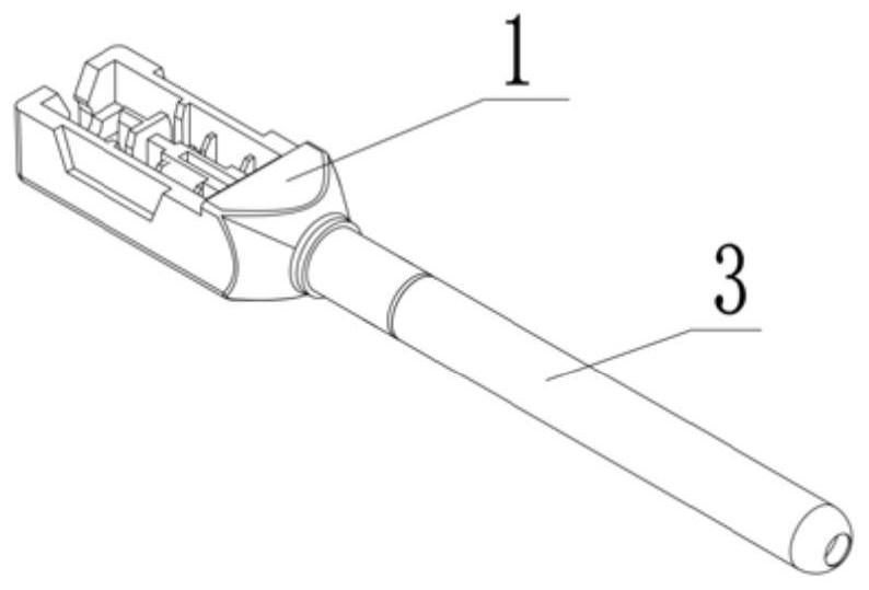
[0051] Such as image 3 As shown, the reinforcing tube 3 is sleeved outside the electric ignition element 2 , and the opening end of the reinforcing tube 3 is engaged or glued to the small diameter section of the bayonet plug of the electric detonator of the insulating connector 1 . The basic detonator 4 is set outside the reinforcing tube 3, and the end of the basic detonator 4 is engaged or bonded with the large-diameter section of the electric detonator bayonet plug of the insulating connector 1 to form a sealed structure.

[0052] The insulated connector 1 is extended through the metal terminals 1-1 and clamping terminals 1-2 at both ends, and is electrically connected with ...

Embodiment 3

[0054] On the basis of Embodiment 1 or Embodiment 2, the electric detonator is clamped with the extension leg 5 through the clamping terminal 1-2 on the insulating connector 1, and the extension leg 5 and its junction box are added to form A self-contained and integrated electric detonator, such as Figure 4 , Figure 5 shown.


PUM


Abstract

The invention discloses a portable electric detonator. The portable electric detonator comprises an insulating connecting piece, an electric ignition element and a basic detonator; one end of the insulating connecting piece is a structure with the outer sides of metal terminals being wrapped with an insulating elastic material and serves as an electric detonator bayonet plug, and the other end of the insulating connecting piece is used as a junction box for extending to be connected with a wire; the insulating connecting piece and the electric ignition element are fixedly and mechanically through the exposed metal terminals and achieve electric connection; and the basic detonator is arranged outside the electric ignition element in a sleeving mode, and the end part of the basic detonator is clamped with the electric detonator bayonet plug of the insulating connecting piece to form a sealing structure. According to the portable electric detonator, the production process is efficient and rapid, assembling is easy, and using is safe and convenient.

Description

technical field [0001] The invention relates to the technical field of civil blasting equipment, in particular to a portable electric detonator. Background technique [0002] Industrial detonators are widely used civilian detonators. All detonators that use electricity as the initial stimulus energy to ignite and detonate are detonators that involve electricity, and are referred to as electric detonators for short. In the structure of the electric detonator, the simplest structure is the ordinary electric detonator, and the most important component is the electric igniter. In the electronic detonators developed in recent years, the electric igniter has been transformed into an electronic igniter controlled by an electronic circuit, and these are all electric igniters. Electric ignition parts need to be closely combined with the shell of the basic detonator to form a specific form of sealing structure to ensure that the electric detonator can work reliably in various occasio...

Claims


Application Information

Patent Timeline
Patent Type & Authority Applications(China)
IPC IPC(8): F42C19/12
CPCF42C19/12
Inventor 柳勤张连壮任庆国
Owner 北京凯米迈克科技有限公司
Learn More