Eureka AIR delivers breakthrough ideas for toughest innovation challenges, trusted by R&D personnel around the world.

Inertial positioning and orientation equipment inertial measurement unit parameter temperature compensation calibration method

A technology for inertial positioning and orientation equipment, which is used in measurement devices, instruments, and navigation through velocity/acceleration measurement. effect of speed

Pending Publication Date: 2021-10-01
HUBEI SANJIANG AEROSPACE WANFENG TECH DEV
View PDF6 Cites 1 Cited by
  • Summary
  • Abstract
  • Description
  • Claims
  • Application Information

AI Technical Summary

Problems solved by technology

[0003] The inertial group body is mainly composed of two parts: gyroscope and accelerometer. Since the accuracy of the inertial group body gyroscope and accelerometer is easily affected by temperature, under different temperature conditions, the gyroscope and acceleration information output by the inertial group have large deviations. The traditional method Take temperature control measures to make the product work at a constant temperature point to ensure output accuracy, but it takes a long time to control the ambient temperature of the inertial positioning and orientation equipment to the required temperature
With the continuous improvement of the application requirements of inertial positioning and orientation equipment, the existing temperature control methods can no longer meet the application requirements

Method used


Image

  • Inertial positioning and orientation equipment inertial measurement unit parameter temperature compensation calibration method
  • Inertial positioning and orientation equipment inertial measurement unit parameter temperature compensation calibration method

Examples


Embodiment Construction

[0049] In order to make the object, technical solution and advantages of the present invention clearer, the present invention will be further described in detail below in conjunction with the accompanying drawings and embodiments. It should be understood that the specific embodiments described here are only used to explain the present invention, not to limit the present invention. In addition, the technical features involved in the various embodiments of the present invention described below can be combined with each other as long as they do not constitute a conflict with each other. The present invention will be further described in detail below in combination with specific embodiments.

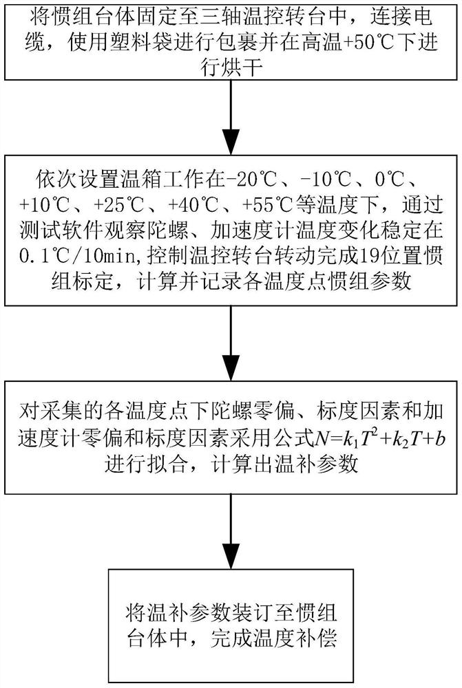
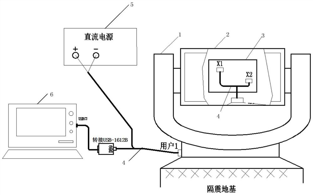
[0050] As a preferred embodiment of the present invention, such as Figure 1-2 as shown, figure 1 A flow chart of a calibration method for inertial positioning and orientation equipment inertial set parameter temperature compensation provided by the embodiment of the present invention; f...


PUM


Abstract

The invention discloses an inertial positioning and orientation equipment inertial measurement unit parameter temperature compensation calibration method, which comprises the following steps of: fixing an inertial measurement unit table body into an incubator of a three-axis temperature control turntable, connecting a cable, and drying before testing; sequentially setting the temperature box to work at a plurality of different test temperatures, controlling the three-axis temperature control turntable to rotate to complete 19-position inertial measurement unit calibration by adopting a 19-position iterative calibration method after the actual temperature change is stable, and calculating and recording each inertial measurement unit parameter at each actual temperature point; and fitting by adopting a formula N=k1T2+k2T+b, calculating a temperature compensation parameter, and binding the temperature compensation parameter into the inertial measurement unit table body to finish temperature compensation. Through linear fitting, compensation of the inertial measurement unit table body in a full temperature range is completed, so that a product can be subjected to cold start at any working temperature, a system can be ensured to work for a long time and with high precision, and the reaction speed of the product is greatly improved.

Description

technical field [0001] The invention belongs to the technical field of inertial positioning and orientation testing, and in particular relates to a temperature compensation calibration method for inertial set parameters of inertial positioning and orientation equipment. Background technique [0002] The inertial positioning and orientation equipment is mainly composed of an inertial group platform, a servo system and related circuits. It is mainly used to provide real-time position information such as true north azimuth, longitude, latitude, and elevation for weapon systems such as launch vehicles. The accuracy of the inertial positioning and orientation equipment will be It directly affects the strike accuracy of weapon systems such as launch vehicles on targets. [0003] The inertial unit body is mainly composed of two parts: gyroscope and accelerometer. Since the accuracy of the inertial unit body gyroscope and accelerometer is easily affected by temperature, under differ...

Claims


Application Information

Patent Timeline
Patent Type & Authority Applications(China)
IPC IPC(8): G01C21/16G01C21/20G01C25/00
CPCG01C21/16G01C21/20G01C25/00
Inventor 曹海波张书文左庆吕振宇万洋冯建凡李娜
Owner HUBEI SANJIANG AEROSPACE WANFENG TECH DEV
Why Eureka
Eureka Blog
Learn More