A heat shrink curing device

A curing device and heat shrinking technology, applied in the directions of instruments, optics, light guides, etc., can solve the problems of low heat shrinkage curing efficiency and heat loss of heat conduction blocks, so as to improve the heat shrinkage curing efficiency, uniform heating, and improve the heat shrinkage curing efficiency. effect of effect

Active Publication Date: 2022-07-15
SHENZHEN ADTEK TECH CO LTD
View PDF5 Cites 0 Cited by
  • Summary
  • Abstract
  • Description
  • Claims
  • Application Information

AI Technical Summary

Problems solved by technology

[0004] In view of the related technologies mentioned above, the inventor believes that when the workshop temperature is low, the heat exchange rate is too high, and the heat of the heat conduction block is easily lost to the outside air, resulting in low heat shrinkage and curing efficiency

Method used


Image

  • A heat shrink curing device
  • A heat shrink curing device
  • A heat shrink curing device

Examples


Embodiment 2

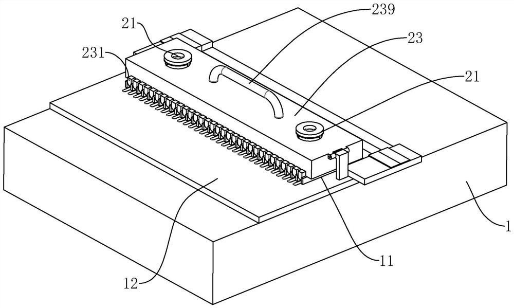
[0048] Embodiment 2, differs from embodiment 1 in that, as image 3 , Figure 4 As shown, the mobile hot air assembly 2 includes a bar-shaped housing 23, a hot air blower 21 and a driving mechanism, wherein the hot air blower 21 is fixed on the upper surface of the bar-shaped housing 23, and the air outlet end of the hot air blower 21 is connected to the bar-shaped housing 23. Communication, that is, the hot air blower 21 is used to inject positive pressure hot air into the inner cavity of the bar-shaped housing 23 .

[0049] like image 3 As shown, the length direction of the bar-shaped housing 23 is arranged along the length direction of the heat-conducting block 11, one end of the bar-shaped housing 23 is hingedly connected with the heating furnace body 1, and the upper surface of the bar-shaped housing 23 is provided with a heat-resistant silicone rubber material. The handle 239 is formed, and the handle 239 is used to drive the bar-shaped housing 23 to turn over; the si...

Embodiment 3

[0058] Embodiment 3, on the basis of embodiment 2, make the following settings, as Figure 10 As shown, the two opposite wide sides of the wind deflector 233 are provided with a plurality of follower plates 25, the follower plates 25 are thin metal plates, the follower plates 25 and the wind deflector 233 are arranged at the same length, and one length of the follower plate 25 is equal. The side edges and the wind deflector 233 are hingedly connected through hinges.

[0059] When the wind deflector 233 rotates, the follower plate 25 is partially in a vertical state and partially adheres to the surface of the wind deflector 233 due to gravity, and the follower plate 25 in the vertical state can guide the hot air to a certain extent. function, so that the hot air in the bar-shaped housing 23 can be concentrated as much as possible, so as to improve the effect of centralized heating.


PUM


Abstract

The application relates to a heat shrinkage curing device, comprising a heating furnace body and a mobile hot air assembly, wherein the heating furnace body is provided with a heat conducting block, and the heat conducting block is provided with a plurality of positioning grooves arranged at intervals and used for placing optical fibers; The air outlet end of the mobile hot air assembly is located above the positioning groove, and the air outlet end of the mobile hot air assembly moves along the arrangement direction of the positioning groove. In the present application, by arranging a mobile hot air component, the optical fiber can be supplemented by mobile heating, thereby improving the efficiency of heat shrinkage and curing, and uniformly heating, so as to improve the effect of heat shrinkage and curing.

Description

technical field [0001] The present application relates to the field of optical fiber processing equipment, and in particular, to a heat shrink curing device. Background technique [0002] Fiber curing furnace is a common equipment in optical fiber processing and production. Production processes for heating, resin curing and drying of parts in various other industries. [0003] The specific heating and curing method is as follows: the optical fiber is fixed in the fixture, and the to-be-heated part of the optical fiber is located in the positioning groove of the heat-conducting block. [0004] In view of the above-mentioned related technologies, the inventor believes that when the temperature of the workshop is low, the heat exchange rate is too high, and the heat of the heat conducting block is easily lost to the outside air, resulting in low heat shrinkage and curing efficiency. SUMMARY OF THE INVENTION [0005] In order to improve the heat shrinkage curing efficiency, ...

Claims


Application Information

Patent Timeline
Patent Type & Authority Patents(China)
IPC IPC(8): G02B6/38G02B6/287
CPCG02B6/38G02B6/287
Inventor 马奎李宝荣余振龙
Owner SHENZHEN ADTEK TECH CO LTD
Why Eureka
Try Eureka