Manual clamping intelligent welding tool for heavy hammer tensioning support of mine belt conveyor

A belt conveyor, welding tooling technology, applied in welding equipment, auxiliary welding equipment, welding/cutting auxiliary equipment, etc., can solve the problems of high welding requirements, physical injury of welding personnel, and inability to achieve high-efficiency welding effect, health protection, fast and welding effect

Inactive Publication Date: 2021-10-08
山东海纳智能装备科技股份有限公司
View PDF6 Cites 0 Cited by
  • Summary
  • Abstract
  • Description
  • Claims
  • Application Information

AI Technical Summary

Problems solved by technology

[0003] Existing belt conveyors are widely used in mining operations. The bottom of the belt conveyor is generally welded and installed with brackets. The existing brackets are welded by ordinary welding tools, which is inefficient and cannot meet high welding requirements. At the same time The welding requirements during the welding process can easily cause damage to the welder's body, so it needs to be improved

Method used


Image

  • Manual clamping intelligent welding tool for heavy hammer tensioning support of mine belt conveyor
  • Manual clamping intelligent welding tool for heavy hammer tensioning support of mine belt conveyor
  • Manual clamping intelligent welding tool for heavy hammer tensioning support of mine belt conveyor

Examples


Embodiment Construction

[0026] The following will clearly and completely describe the technical solutions in the embodiments of the present invention with reference to the accompanying drawings in the embodiments of the present invention. Obviously, the described embodiments are only some, not all, embodiments of the present invention. Based on the embodiments of the present invention, all other embodiments obtained by persons of ordinary skill in the art without making creative efforts belong to the protection scope of the present invention.

[0027] In the present invention, unless otherwise clearly specified and limited, terms such as "installation", "connection", "connection" and "fixation" should be understood in a broad sense, for example, it can be a fixed connection or a detachable connection , or integrated; it can be mechanically connected or electrically connected; it can be directly connected or indirectly connected through an intermediary, and it can be the internal communication of two c...


PUM


Abstract

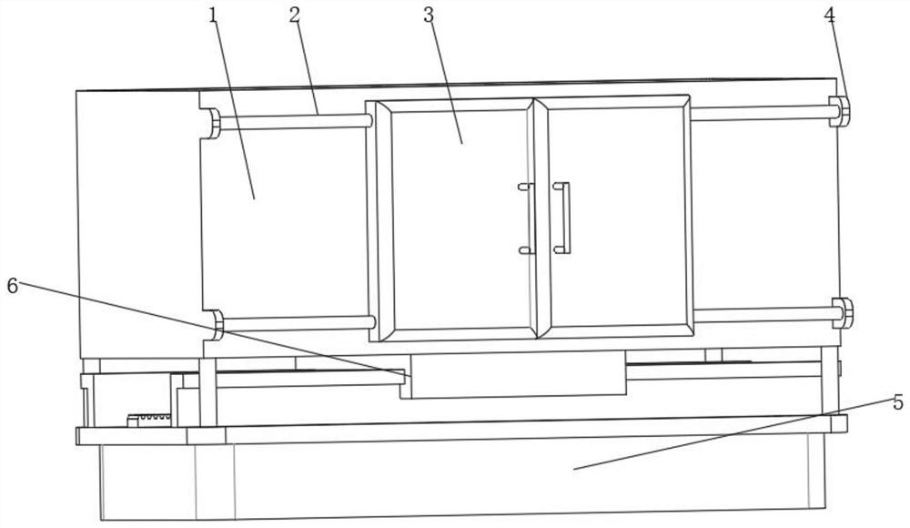
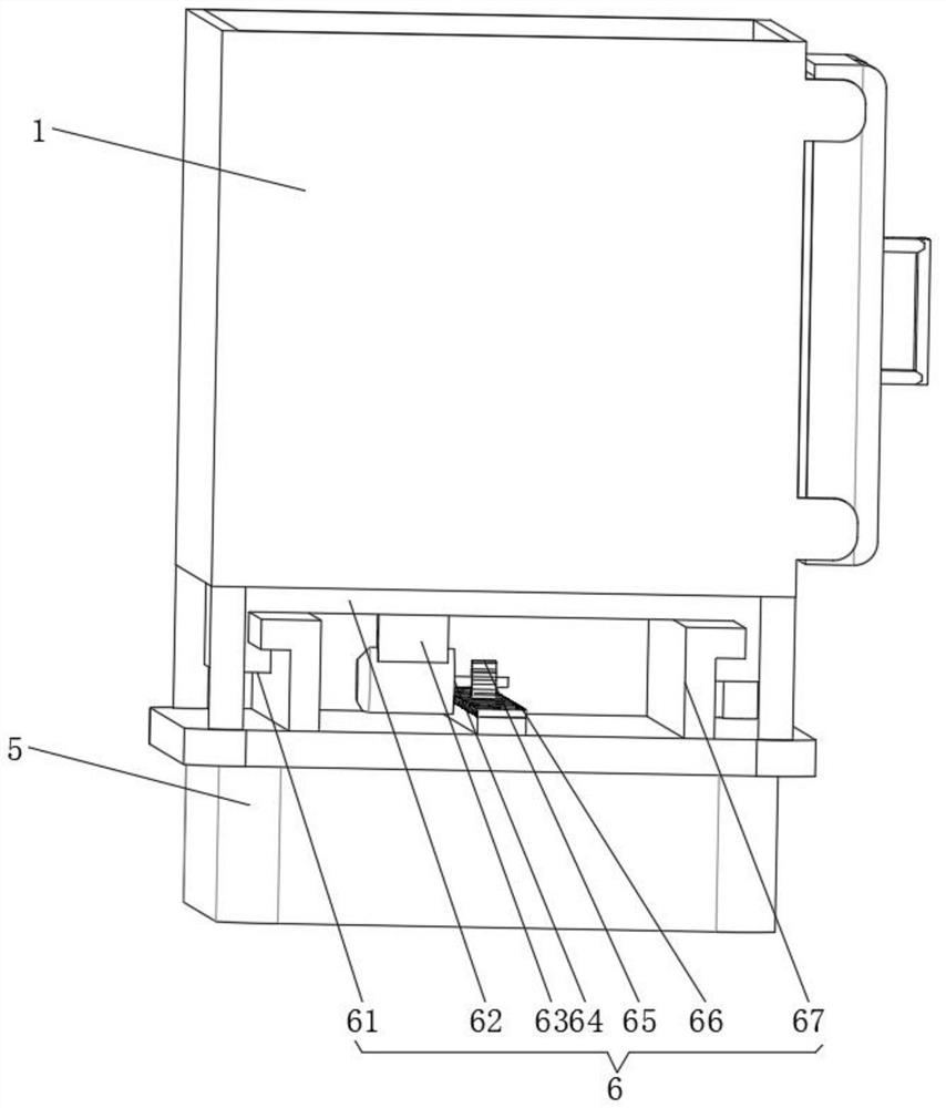
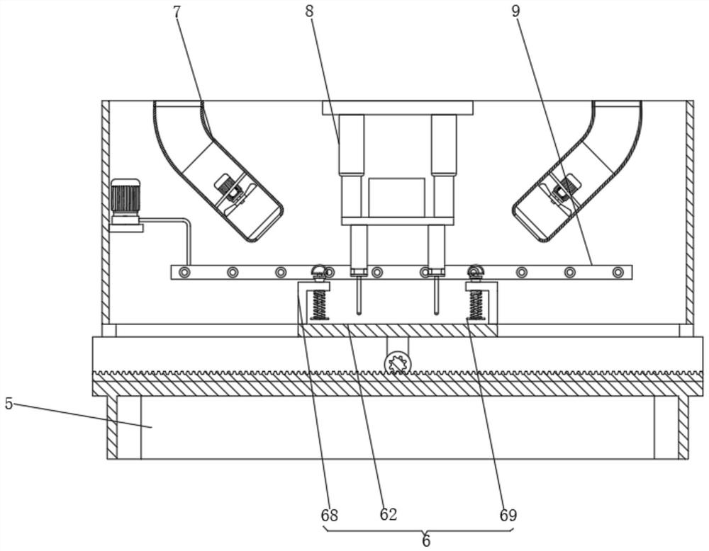
The invention relates to the technical field of welding tools, and discloses a manual clamping intelligent welding tool for the heavy hammer tensioning support of a mine belt conveyor. The manual clamping intelligent welding tool comprises a base, a movable clamping mechanism is fixedly connected to the top of the base, a shell is fixedly connected to the four corners of the top of the base, and supporting blocks are fixedly connected to the four corners of the front face of the shell. A sliding rod is fixedly connected to the inner side of the supporting block, an operation door is slidably connected to the middle of the sliding rod, and a welding mechanism is fixedly connected to the middle in the shell. According to the manual clamping intelligent welding tool for the heavy hammer tensioning support of the mine belt conveyor, through the arranged movable clamping mechanism, a clamping block can be conveniently away from an operation plate through pulling of a pull ring, at the moment, a welding piece is conveniently placed on the top of the operation plate, the pull ring is loosened, and the welding piece is clamped and fixed to the top of the operation plate through the clamping block under the action of a spring; and meanwhile, a motor is started to drive a gear to rotate, the operation plate can move left and right on a sliding rail under cooperation of the gear, and therefore the high-requirement welding purpose is achieved.

Description

technical field [0001] The invention relates to the technical field of welding tooling, in particular to an intelligent welding tooling for manual clamping of a heavy hammer tensioning bracket of a belt conveyor in a mine. Background technique [0002] Belt conveyors, also known as belt conveyors, are widely used in various industries such as home appliances, electronics, electrical appliances, machinery, tobacco, injection molding, post and telecommunications, printing, food, etc., for the assembly, testing, debugging, packaging and transportation of objects. Line body transportation can be selected according to process requirements: ordinary continuous operation, rhythmic operation, variable speed operation and other control methods; line body selection according to local conditions: line body forms such as straight lines, curves, and slopes. The conveying equipment includes: belt conveyors, also known as belt conveyors Conveyors or belt conveyors are indispensable economi...

Claims


Application Information

Patent Timeline
Patent Type & Authority Applications(China)
IPC IPC(8): B23K37/00B23K37/02B23K37/04
CPCB23K37/0443B23K37/00B23K37/0247B23K37/0252B23K37/003
Inventor 辛光明孙凯张佳奖刘伟
Owner 山东海纳智能装备科技股份有限公司
Why Eureka
Try Eureka