Mounting structure and method for reducing thermal deflection of tool tower crane

A technology of installation structure and thermal displacement, which is applied in the direction of positioning device, metal processing machinery parts, clamping, etc., can solve the problems such as the reduction of workpiece accuracy, achieve high processing accuracy, reduce errors, and avoid the effects of thermal expansion

Inactive Publication Date: 2021-10-08
津上精密机床(浙江)有限公司
View PDF9 Cites 0 Cited by
  • Summary
  • Abstract
  • Description
  • Claims
  • Application Information

AI Technical Summary

Benefits of technology

The technical effect of this invention relates to improving the precision with which machines are used for manufacturing parts during production without causing any errors due to variations or misalignments between different tools. This can lead to increased efficiency and productivity while maintaining high quality standards across various industries such as automotive industry where precise part dimensions must be achieved through cutting processes.

Problems solved by technology

This patented describes how different parts can affect the precision of machining processes when they expand due to temperature differences between them caused by factors like material shrinkage that occurs over time.

Method used


Image

  • Mounting structure and method for reducing thermal deflection of tool tower crane
  • Mounting structure and method for reducing thermal deflection of tool tower crane
  • Mounting structure and method for reducing thermal deflection of tool tower crane

Examples


Embodiment Construction

[0037] The following is attached Figure 1-4 The application is described in further detail.

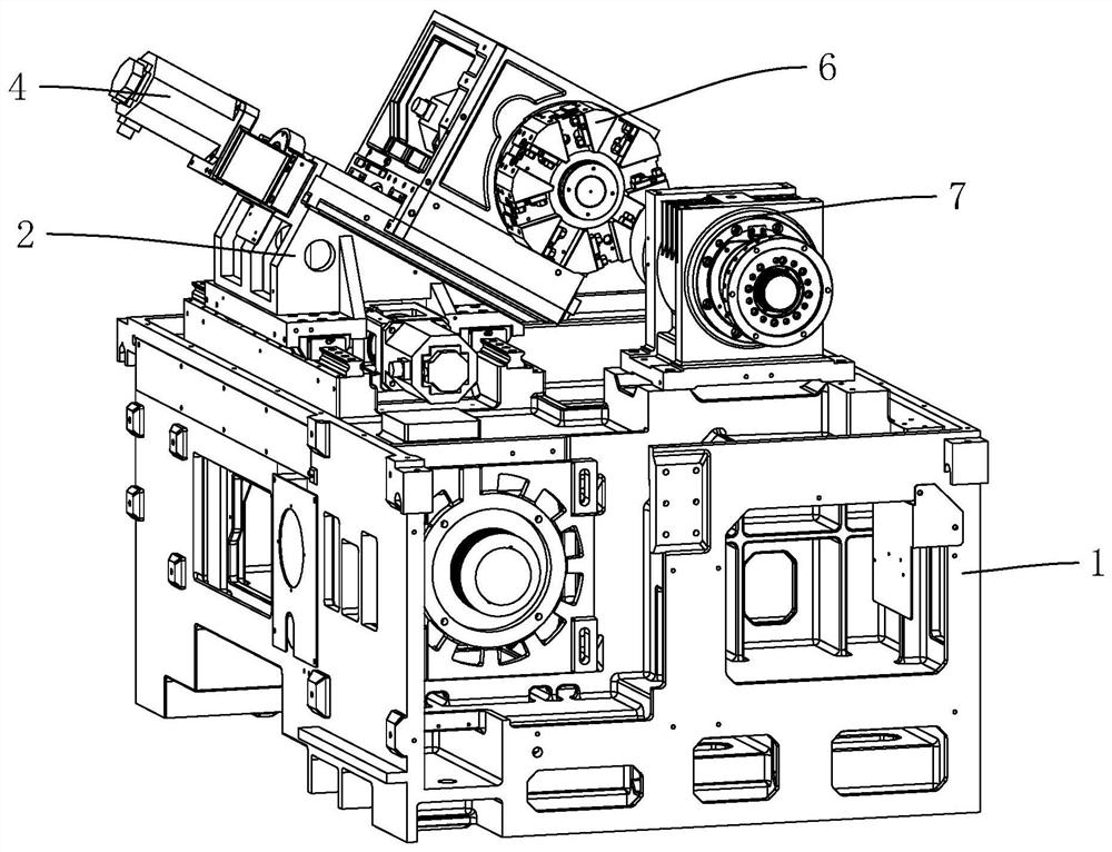
[0038] The embodiment of the present application discloses an installation structure for reducing the thermal displacement of the turret machine, such as figure 1 As shown, including the bed 1, a guide rail is arranged on the bed 1, and a mounting frame 2 is slidably connected to the guide rail, and a screw nut mechanism for controlling the sliding of the mounting frame 2 is also arranged on the bed 1. The screw nut mechanism The impact on the overall machine tool is small, and the lead screw of the screw nut mechanism can be pre-stretched or not pre-stretched.

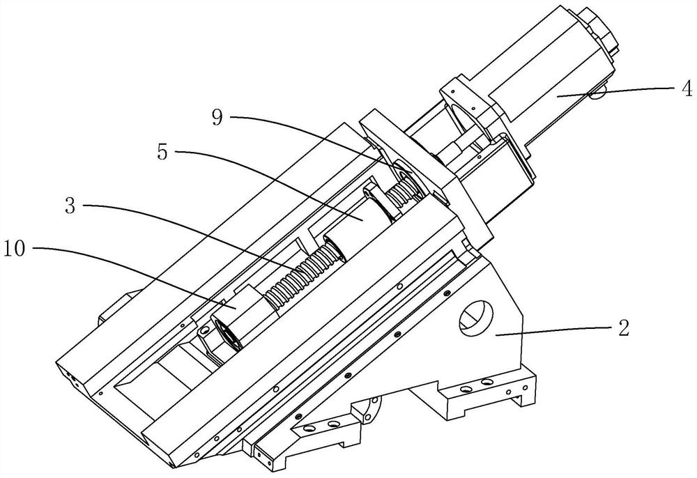
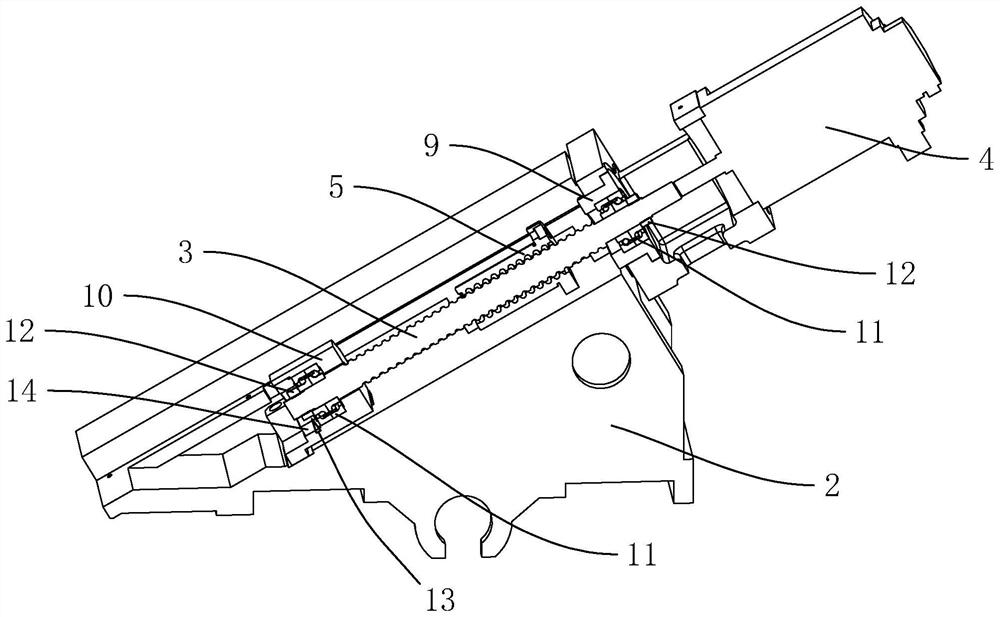
[0039] combine figure 2 and image 3 As shown, the large bearing seat 9 and the small bearing seat 10 are installed and fixed on the mounting frame 2 by bolts, and the screw rod 3 is installed on the large bearing seat 9 and the small bearing seat 10. The screw rod 3 has been pre-stretched, and the screw rod 3. Pre-stre...


PUM


Abstract

The invention discloses a mounting structure and method for reducing thermal deflection of a tool tower crane, and relates to the technical field of precision machine tools. According to the technical scheme, the mounting structure for reducing the thermal deflection of the tool turret crane comprises a lathe bed, a mounting frame is arranged on the lathe bed, a lead screw is rotationally connected to the mounting frame, a driving motor for driving the lead screw to rotate is fixed to the mounting frame, a lead screw nut pair is rotationally connected to the lead screw, and a tool tower is slidably connected to the mounting frame. The tool tower is fixedly connected with the lead screw nut pair, a main shaft is arranged on one side of the tool tower, the main shaft is fixed to the lathe bed, the lead screw is pre-stretched to the length after the lead screw is heated and expanded, and an adjusting mechanism is further arranged on the lathe bed, the mounting frame, the tool tower and the main shaft. The adjusting mechanism detects the temperature change of each component, calculates and generates a correction quantity and feeds the correction quantity back to the NC of the machine tool for adjustment. The structure is reasonable, the influence caused by thermal expansion of the machine tool is effectively reduced, and the machining precision of the machine tool is greatly improved.

Description


Claims


Application Information

Patent Timeline
Owner 津上精密机床(浙江)有限公司
Why Eureka
Try Eureka