Hydraulic bearing

a technology of hydraulic bearings and bearings, applied in the field of hydraulic bearings, can solve the problems of deteriorating rigidity, affecting the performance of bearings, and generating great heat due to fluid friction at the land portions, so as to prevent cavitation generated by suction air and restrict the thermal expansion of bearing metals

Inactive Publication Date: 2005-08-30
TOYODA MASCH WORKS LTD
View PDF7 Cites 12 Cited by
  • Summary
  • Abstract
  • Description
  • Claims
  • Application Information

AI Technical Summary

Benefits of technology

[0011]It is an object of the present invention to provide an improved hydraulic bearing.
[0013]Thus, the hydraulic bearing providing the hydrostatic pocket and the land portion functions not only as a hydrostatic bearing but also as a hydrodynamic bearing. Then, since the fluid is drained through the drain hole, thermal expansion of the bearing metal due to heat generation of the fluid is restrained. Moreover, since the anti suctioning unit prevents air from suctioning into the hydraulic bearing, cavitation generated by suctioned air is prevented.

Problems solved by technology

However, in case of high rotating speed, a great heat due to fluid friction is generated at the land portions 7.
This causes such a vicious circle that deteriorate the performance of the bearing.
However, existence of the drain grooves 22 causes deterioration of the rigidity because each land portion 7 is separated and small.
Moreover, the separated type bearing tends to cause cavitation.

Method used


Image

  • Hydraulic bearing
  • Hydraulic bearing
  • Hydraulic bearing

Examples


first embodiment

[First Embodiment]

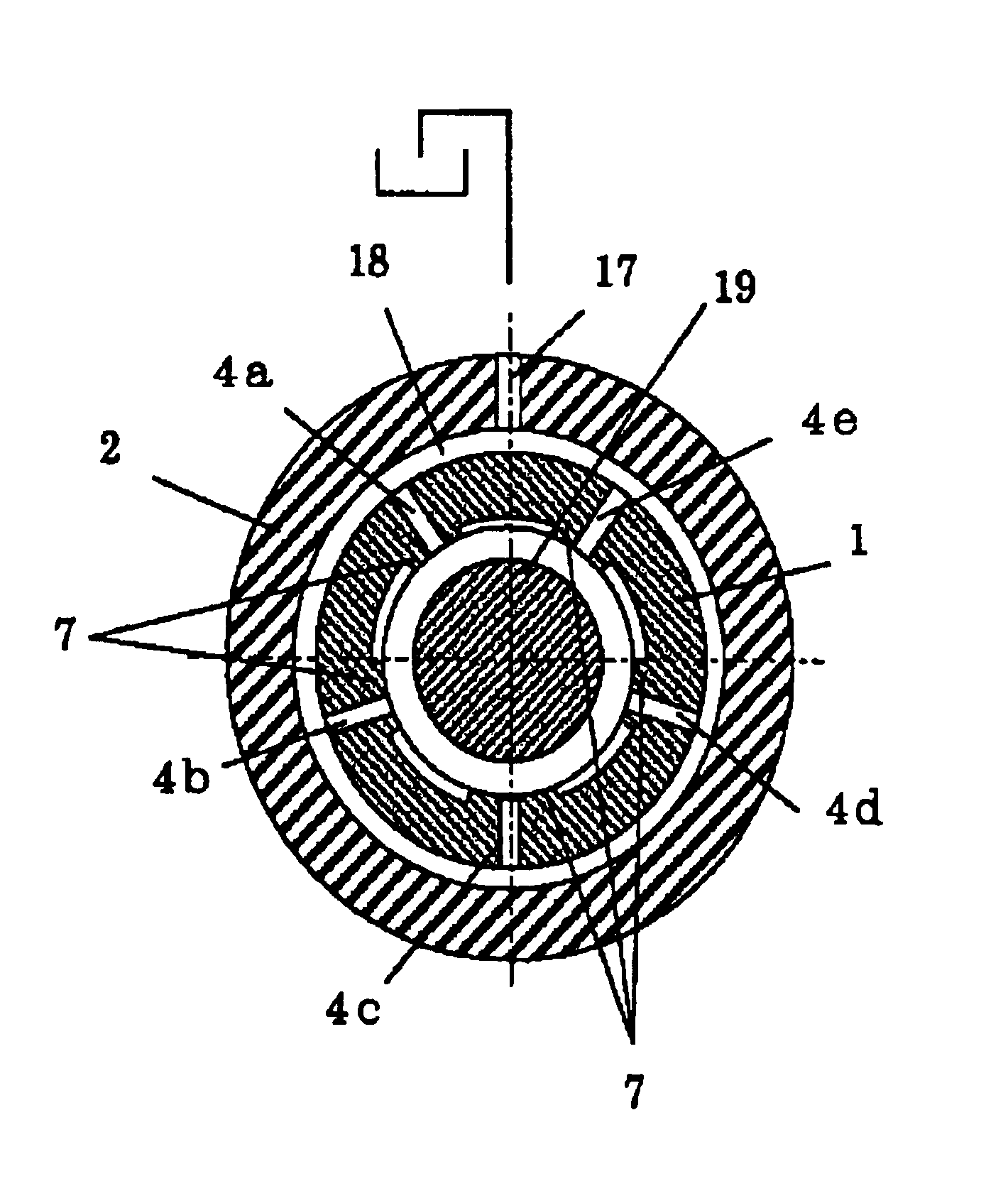
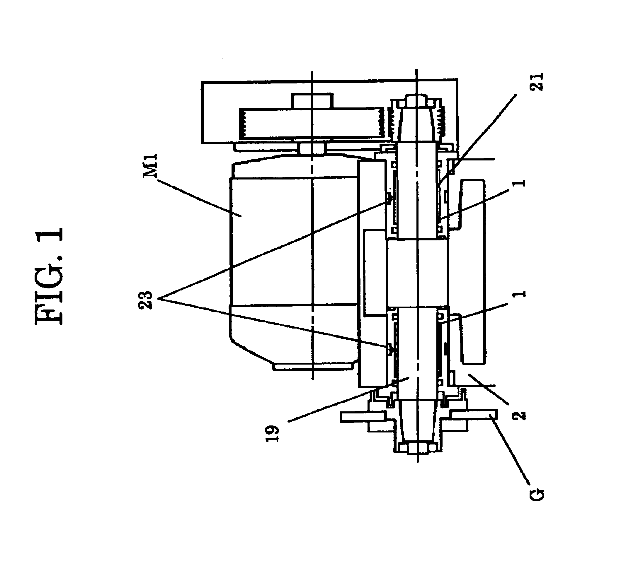
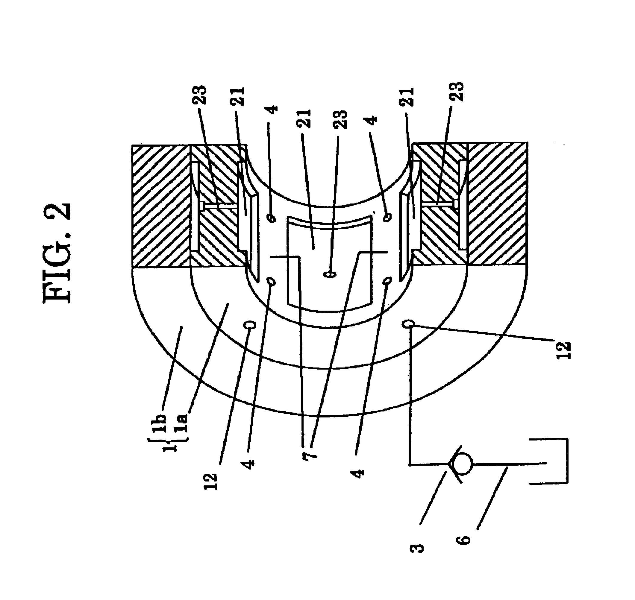
[0028]A radial hydraulic bearing according to the present invention is employed, for instance, in a wheel spindle apparatus of a grinding machine as illustrated in FIG. 1. The hydraulic bearings 1 are arranged at both end portions of a bearing housing 2 to support a wheel spindle 19 as a rotating shaft at inner surfaces thereof. At one end of the wheel spindle 19, a grinding wheel G is attached. A driving belt (not shown in Figures) is tensionally strung between the other end of the wheel spindle 19 and a motor M1 through the driving belt, in which the wheel spindle 19 is rotated by the motor M1. The hydraulic bearings 1 are fixed in the bearing housing 2 by manners of a shrinkage fit or a press fit. At one end of each hydraulic bearing 1, a flange portion is formed and is fixed to the bearing housing 2 by plural bolts. Referring to FIG. 2, the radial hydraulic bearing 1 comprises a ring shape inner sleeve 1a as a bearing metal and a bearing case 1b wherein the inn...

second embodiment

[Second Embodiment]

[0038]Second embodiment according to the present invention will be described hereinafter with reference to the drawings, in which explanation about the same construction as the first embodiment is omitted. Referring to FIG. 9, the hydraulic bearing 1 includes the check valve 3 to prevent air from suctioning when the pressure between the land portion 7 and the wheel spindle 19 becomes negative pressure with same manner as the first embodiment. In addition, the hydraulic bearing 1 includes an oil-suctioning unit 13 to suction lubricant oil at the same time. The oil-suctioning unit 13 is disposed between an oil-suctioning pass 16 formed in the bearing housing 2 and the drain pass 12 connected to the drain holes 4a1 and 4a2. The oil-suctioning unit 13 is, for example, like the check valve 3 turning upside down and includes a valve element 14 biased a spring in a case. The valve clement 14 usually closes an opening 15 because of the spring force.

[0039]The inner surface...

third embodiment

[Third Embodiment]

[0044]Third embodiment according to the present invention will be described hereinafter with reference to the drawings, in which explanation about the same construction as the first and the second embodiment is omitted. Referring to FIG. 10, various sensors are provided for a wheel spindle apparatus of the third embodiment in addition to the constitution of the previous embodiments. An encoder 32, one of the various sensors, is attached on an end portion of the wheel spindle 19 to measure rotating speed of the wheel spindle 19. One or more pressure gauges 33 serving as a sensor are attached at appropriate positions of the land portions 7 to measure pressure thereat. A gap sensor 34 is disposed on the inner surface of the hydraulic bearing 1 to measure a bearing clearance (eccentricity of the wheel spindle 19 relative to the hydraulic bearing 1) therebetween. Each of the sensors 32, 33 and 34 is connected electrically to a controller 31 to input its output therefrom...


PUM


Abstract

A hydraulic bearing that supports a rotating shaft comprises a bearing metal. On a surface of the bearing metal, a hydrostatic pocket and a land portion are formed. The land portion is defined by the hydrostatic pocket and generates hydrodynamic pressure in response to a rotation of the rotating shaft. The hydraulic bearing further comprises a pressure fluid supplying source and an oil-supplying hole. The oil-supplying hole is opened in the hydrostatic pocket and provides pressure fluid from the pressure fluid supplying source to the hydrostatic pocket. On the land portion, a drain hole that drains the fluid is formed. On the way of a drain passage, a check valve is disposed. Since the drain hole does not separate the land portion, deterioration of bearing rigidity is restrained. Further, since the fluid is drained through the drain hole, thermal expansion of the bearing metal due to heat generation of the fluid is restrained. Moreover, according to the check valve, it is possible to prevent suctioning air into the hydraulic bearing when negative pressure generates at the land portion.

Description

INCORPORATION BY REFERENCE[0001]The entire disclosure of Japanese Patent Applications Nos. 2001-294420 filed on Sep. 26, 2001 and 2002-262912 filed on Sep. 9, 2002 including specification, drawings and abstract is herein by reference in its entirety.BACKGROUND OF THE INVENTION[0002]1. Field of the Invention[0003]The invention present relates to a hydraulic bearing that supports a rotating shaft or the like.[0004]2. Description of the Related Art[0005]FIGS. 12(A) to 12(C) are three partially developments showing inner surfaces of bearing metals which constitute radial hydraulic bearings according to the prior arts. Plural hydrostatic pockets 21 having quadrilateral grooves as shown by FIGS. 12(A) and 12(C) or U-shaped grooves as shown by FIG. 12(B) are formed on each inner surface of the bearing metals along a rotational direction of a rotating shaft. An oil-supplying hole 23 is formed in each hydrostatic pocket 21. Land portions 7 formed on the inner surface of the bearing metal exc...

Claims


Application Information

Patent Timeline
Patent Type & Authority Patents(United States)
IPC IPC(8): F16C33/04F16C33/10F16C32/06B23B19/02B24B41/04B23Q1/26B23Q1/38
CPCF16C32/0651F16C32/0659F16C32/0685F16C33/1075
Inventor HIRANO, MINORUSHIMA, TOSHIHIKO
Owner TOYODA MASCH WORKS LTD
Why Eureka
Try Eureka