Fur shearing device

A hair clipper and main body technology, which is applied in the field of hair clippers, can solve the problems of poor heat dissipation and complex cutter head structure, achieve good heat dissipation function, avoid increased battery energy loss, and increase the effect of contact area

Active Publication Date: 2021-10-08
SHENZHEN DOGCARE INNOVATION & TECH CO LTD
View PDF9 Cites 1 Cited by
  • Summary
  • Abstract
  • Description
  • Claims
  • Application Information

AI Technical Summary

Problems solved by technology

[0005] In view of the above-mentioned shortcomings and deficiencies of the prior art, the present invention provides a hair clipper, which solves the problem of complex structure and poor heat dissipation of the existing clipper head question

Method used


Image

  • Fur shearing device
  • Fur shearing device
  • Fur shearing device

Examples


Embodiment 1

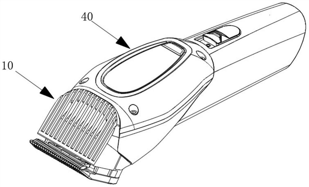
[0068] refer to Figure 1 to Figure 6 The hair clipper of this embodiment includes a main body 40 and a cutter head assembly 10 fixed on the front side of the main body 40 .

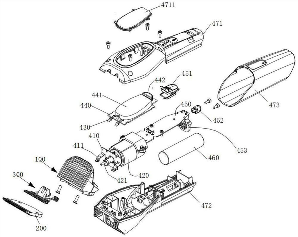
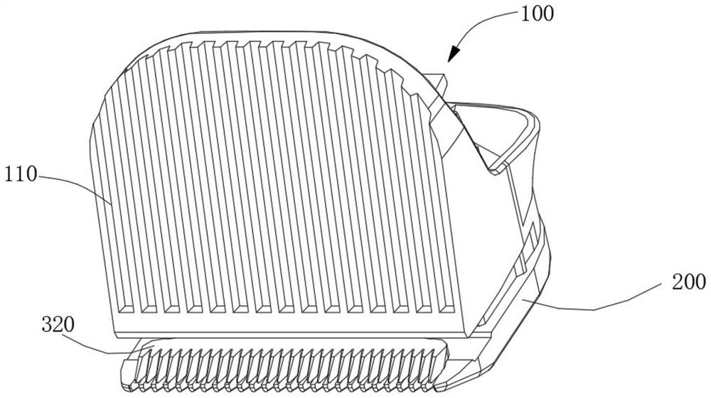
[0069] Such as Figure 3 to Figure 6 As shown, the cutter head assembly 10 includes a heat sink 100 , a stationary blade 200 and a moving blade assembly 300 .

[0070] The heat sink 100 includes a heat sink 110 and a mounting structure 120 . Wherein, the heat dissipation plate 110 is plate-shaped, and its upper end is inclined toward the main body 40 , that is, it is inclined backward. A heat dissipation structure and a light transmission structure are provided on the front surface of the heat dissipation plate 110 . In practical application, in order to improve the heat dissipation effect, the heat dissipation structure may be a wavy or elongated heat sink. Open slots can be arranged between the heat sinks to form a light-transmitting structure.

[0071] The left and right side walls of the cooling...

Embodiment 2

[0104] On the basis of Embodiment 1, the hair clipper of this embodiment is proposed, and the display module in Embodiment 1 is replaced by a working status indicator light and a blade life indicator light.

[0105] refer to Figure 7 and Figure 8 , in this embodiment, the working status indicator light includes a power indicator light 482 and a working mode indicator light 483 . The power indicator light 482 and the blade life indicator light 481 are arranged on the front side of the light control circuit board 440 , and the working mode indicator light 483 is arranged on the rear side of the light control circuit board 440 . Wherein, the working mode indicator light 483 includes a plurality of indicator lights arranged side by side, and indicates different working modes of the hair clipper according to the number of lighted indicator lights, for example, when there are fewer lighted indicator lights, it represents a silent working mode When all the indicator lights of the...


PUM


Abstract

The invention relates to a fur shearing device and belongs to the field of pet supplies. The fur shearing device comprises a main body and a cutting head assembly, wherein a motor is arranged in the main body, an eccentric shaft of the motor extends out of the front end of the main body, the cutting head assembly comprises a heat dissipation device, a static cutter and a movable cutter assembly, the heat dissipation device comprises a heat dissipation plate and an installing structure, a vertically-through containing cavity is formed in the front side of the installing structure, the static cutter is fixed on a bottom plate of the installing structure, the movable cutter assembly comprises a torsion spring, a movable cutter holder and a movable cutter, the movable cutter is fixed on the movable cutter holder, a connecting structure is arranged at the rear end of the movable cutter holder, the movable cutter assembly is arranged in the containing cavity, the movable cutter makes contact with the static cutter, one end of the torsion spring is fixed on the installing structure and the other end is fixed on the movable cutter, the cutting head assembly is fixed to the front end of the mian body, and the eccentric shaft movably matches with the connecting structure of the movable cutter holder. The fur shearing device has the beneficial effects that the structure of the cutting head assembly is simplified, heat dissipation is good, the situation that a pet feels uncomfortable or even scalded due to the fact that the cutting head is too hot is avoided, the matching degree of the pet is improved, and user experience is better.

Description

technical field [0001] The invention relates to the technical field of pet products, in particular to a hair clipper. Background technique [0002] In the process of keeping pets, people usually need to cut their hair regularly for the health of pets and to make pets more lovely. Therefore, hair clippers have become an indispensable tool for raising pets. [0003] At present, most commonly used hair clippers are electric hair clippers, which include a main body and a cutter head assembly. The main body of the body is provided with a motor, which can drive the electric push head located in the cutter head assembly to move. Since the friction between the stationary blade and the moving blade causes the temperature to rise during the working process of the electric push head, a cooling device needs to be provided on the cutter head assembly. However, in the prior art, the cooling device is arranged on the tool holder of the cutter head, which not only increases the complexity ...

Claims


Application Information

Patent Timeline
Patent Type & Authority Applications(China)
IPC IPC(8): B26B19/24B26B19/38B26B19/46
CPCB26B19/24B26B19/46B26B19/3873B26B19/3806B26B19/388
Inventor 范亚华刘堉范德强
Owner SHENZHEN DOGCARE INNOVATION & TECH CO LTD
Why Eureka
Try Eureka