
Holographic diffraction sighting telescope

A sighting scope and holographic technology, applied in the field of optical sighting scopes, can solve problems such as laser wavelength drift, aiming image blur, twin images, etc., and achieve the effects of improving clarity, reducing focal length, and improving aiming accuracy

Pending Publication Date: 2021-10-08
厦门祺丰海派光学科技有限公司
View PDF0 Cites 0 Cited by
  • Summary
  • Abstract
  • Description
  • Claims
  • Application Information

AI Technical Summary

Problems solved by technology

[0003] The present invention provides a holographic diffraction sight for the problems that the existing sight cannot overcome the drift of the center wavelength of the laser, which leads to blurred aiming images, low brightness, and twin images.

Method used


Image

  • Holographic diffraction sighting telescope
  • Holographic diffraction sighting telescope
  • Holographic diffraction sighting telescope

Examples


Embodiment Construction

[0025] Existing scopes cannot overcome the drift of the center wavelength of the laser, which leads to problems such as blurred aiming images, low brightness, and twin images. Therefore, the present invention proposes a new solution. For a clearer representation, the present invention will be described in detail below in conjunction with the accompanying drawings.

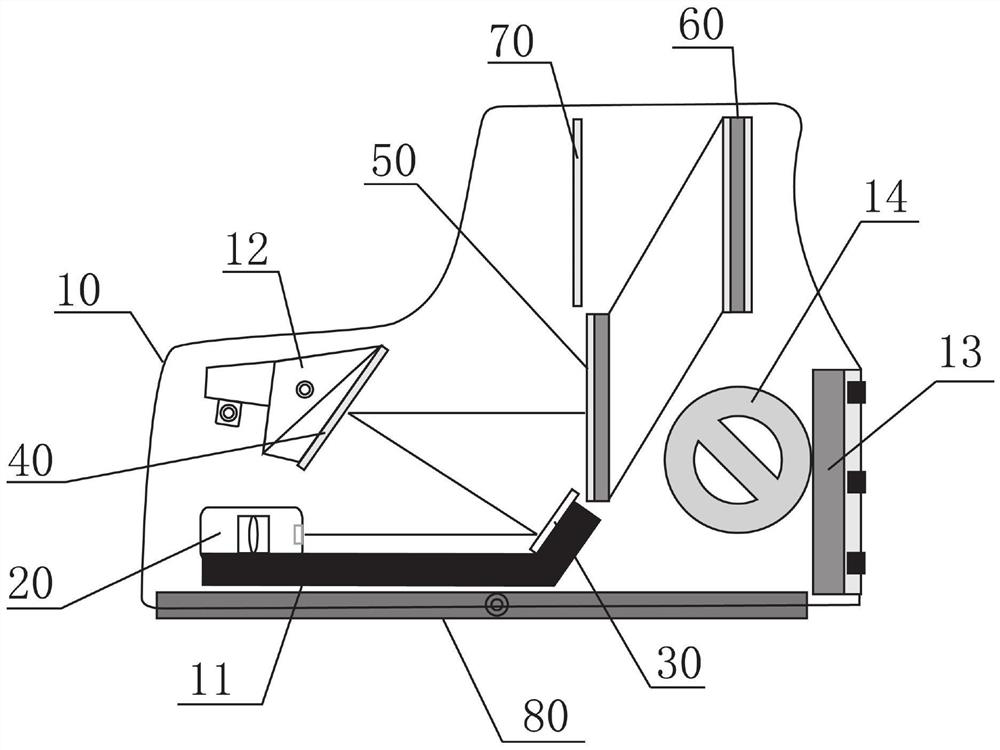
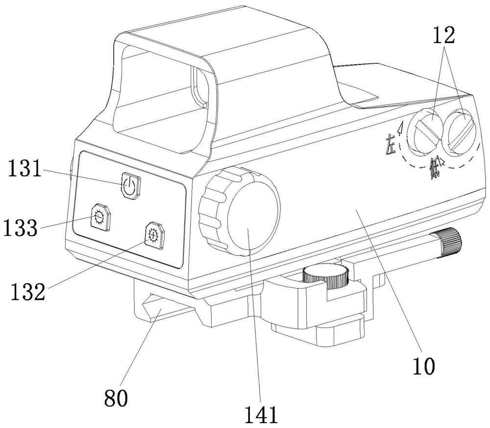
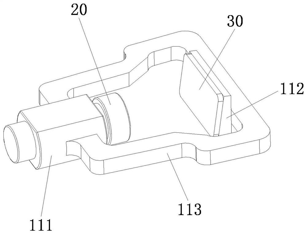
[0026] see Figure 1-2 , a holographic diffraction sight, comprising a mirror body 10, the mirror body 10 is provided with a laser 20 for emitting diffused light, a first reflector 30 for reflecting the diffused light once, and a first reflection mirror 30 for diffusing the light The second reflection mirror 40 for secondary reflection, the H diffraction grating filter 50 for filtering the diffused light and deriving parallel light, and the F holographic image window for dividing the parallel light into a holographic aiming image in the horizontal direction 60. The laser 20 is located on the same horizontal line ...


PUM


Abstract

The invention provides a holographic diffraction sighting telescope. The holographic diffraction sighting telescope comprises a telescope body, wherein a laser used for emitting diffused light, a first reflecting mirror used for reflecting the diffused light for the first time, a second reflecting mirror used for reflecting the diffused light for the second time, an H diffraction grating filter plate used for filtering diffused light and deriving parallel light and an F holographic image window plate used for differentiating the parallel light into a holographic aiming image in the horizontal direction are arranged in the mirror body, and the diffused light emitted by the laser sequentially passes through the first reflecting mirror, the second reflecting mirror and the H diffraction grating filter plate and then reaches the F holographic image window plate to form the holographic aiming image for human eyes to observe. The definition of the holographic aiming image can be effectively improved, the problem of laser center wavelength drift is solved, the situations of focal length, aberration, parallax, large aiming split drawing image blurring noise, low brightness, generation of twin images and the like are reduced, and the aiming precision is improved.

Description

technical field [0001] The invention relates to the field of optical sights, in particular to a holographic diffraction sight. Background technique [0002] The holographic diffraction sight is a revolutionary quick-sight sight that directly observes the point of impact and uses the point of impact as an aiming mark. It has fast aiming, high-precision shooting, and can be used normally in extreme environments. It can be equipped with various guns, howitzers, rocket launchers, etc. on equipment. At present, the domestic holographic diffraction collimator cannot effectively overcome the drift of the laser center wavelength, which limits the further improvement of the laser collimation accuracy, which directly leads to focal length, aberration, parallax, aiming image blur, noise, low brightness, and twinning Phenomena such as imagery, so that there is a large error in aiming, and it cannot be used in actual combat. Contents of the invention [0003] The present invention pr...

Claims


Application Information

Patent Timeline
Patent Type & Authority Applications(China)
IPC IPC(8): F41G1/46F41G1/34F41G1/00
CPCF41G1/46F41G1/34F41G1/00
Inventor 贺叶叶苏金练林琪柠
Owner 厦门祺丰海派光学科技有限公司
Learn More