
Laser marking equipment for digital surveying and mapping

A technology for laser marking and equipment, which is used in surveying, mapping and navigation, measuring devices, measuring instruments, etc., can solve the problems of inconvenient carrying and use of devices, affecting measurement accuracy, and affecting the permeability of the laser output end shell, etc., to avoid Intrusion of stains, protection from erosion, and high convenience

Pending Publication Date: 2021-10-08
宋朋
View PDF1 Cites 0 Cited by
  • Summary
  • Abstract
  • Description
  • Claims
  • Application Information

AI Technical Summary

Problems solved by technology

[0004] The existing device needs to be placed on a relatively flat surface before it can be used, so the staff needs to carry the bracket with them, and the bracket needs to be installed first when measuring, which will cause the device to be carried and used. It is extremely inconvenient. Furthermore, most of the existing devices are used in places with a lot of dust and stains, so that the shell of the laser output end is inevitably contaminated with dust and stains during use, which will affect the communication of the shell of the laser output end. The permeability will affect its measurement accuracy. In view of this, we propose a laser marking equipment for digital surveying and mapping.

Method used


Image

  • Laser marking equipment for digital surveying and mapping
  • Laser marking equipment for digital surveying and mapping
  • Laser marking equipment for digital surveying and mapping

Examples


Embodiment Construction

[0028] In the description of the invention, it is to be understood that the terms "center", "longitudinal", "horizontal", "length", "width", "thickness", "upper", "under", "front", " After "," left "," right "," vertical "," horizontal "," top "," bottom "," inside "," outside "," clockwise "," counterclockwise "or other indication or The positional relationship is based on the orientation or positional relationship shown in the drawings, which is intended to facilitate the description of the present invention and simplified description, rather than indicating or implying that the device or component must have a particular orientation, and is constructed and operated in a particular direction. It is therefore not to be understood to limit the limitations of the invention.

[0029] In the description of the invention, the meaning of "multiple" is two or more, unless otherwise specifically defined.

[0030]In the description of the present invention, it is to be noted that the term ...


PUM


Abstract

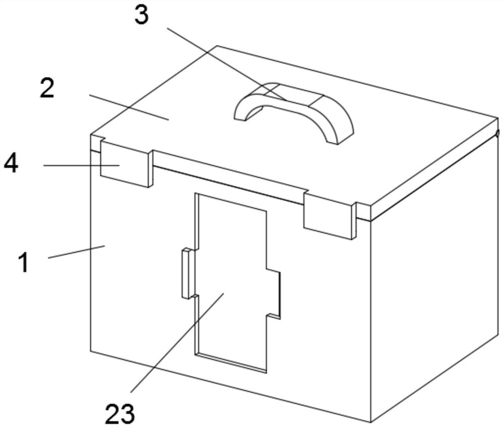
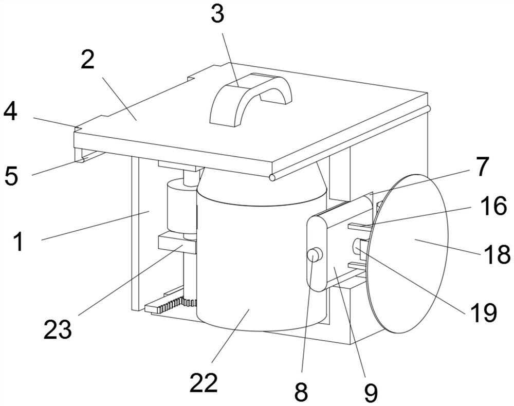
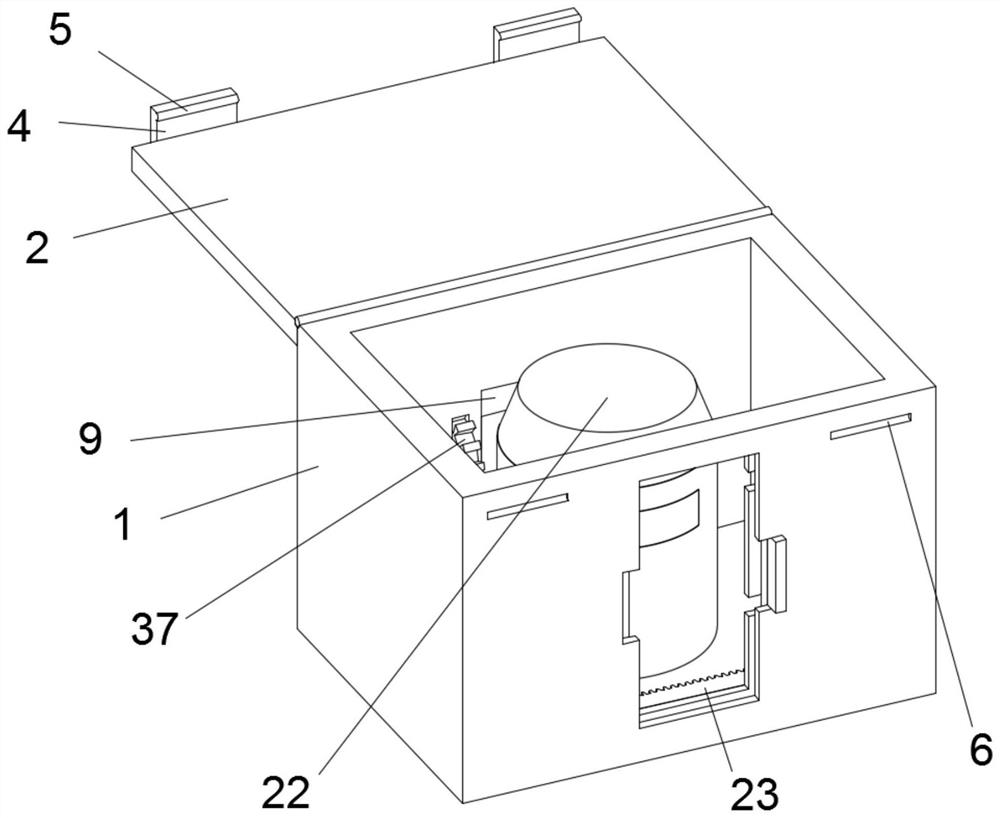
The invention discloses laser marking equipment for digital surveying and mapping, and belongs to the technical field of surveying and mapping equipment. The laser marking equipment for digital surveying and mapping comprises a box body, a plurality of clamping grooves are annularly formed in the positions, relative to clamping blocks, of the outer wall of the circumference of a rotary disc at equal intervals, two supporting columns are fixedly arranged on the rear wall of a rotary plate in a vertically symmetrical structure, a base is fixedly arranged between the rear ends of the two supporting columns, a suction cup is fixedly arranged on the rear wall of the base, and a fixing shaft is fixedly arranged in the middle of the front wall of the suction cup. A shifting plate is hinged to the middle of the fixed shaft relative to the front side of the base through an axis; and a digital laser level gauge body is fixedly arranged in the middle of the bottom face in the box body, and a dustproof wiping assembly is arranged on the front side in the box body. The laser marking equipment can prevent the output end of the digital laser level gauge main body from being contaminated by dust and stains to affect the permeability of the digital laser level gauge main body to the greatest extent, and can be quickly put into use without being supported and lifted by an external bracket, so that the measurement work is greatly facilitated, and the convenience is high.

Description

Technical field [0001] The present invention relates to the field of surveying and mapping apparatus, and more particularly to a digital mapping laser line device. Background technique [0002] The laser marking instrument is a laser level, is an alignometer that is introduced into the gauge of the laser device into the level of the laser device, which is usually used in the horizontal permeability of the axis, and is usually used for home decoration measurement levels, digital laser level It is currently the state-of-the-art level, with special bar level, automatically obtains the barcode reading of the level through the digital imaging system built-in, and no longer needs manual reading. [0003] According to the inspection, the disclosure of which is a patent of CN11895982A discloses a digitally mapping laser line device, and the positioning cooperation between the positioning hole and the beam can increase the positioning accuracy of the design, through the first bracket and ...

Claims


Application Information

Patent Timeline
IPC IPC(8): G01C15/00
CPCG01C15/00Y02A90/30
Inventor 宋朋
Owner 宋朋
Learn More