
Self-focusing lens refractive index distribution detection system and method

A self-focusing lens and refractive index distribution technology, applied in the field of optical measurement, can solve the problems of poor anti-environmental interference ability and low refractive index detection accuracy.

Pending Publication Date: 2021-10-08
SUZHOU UNIV
View PDF1 Cites 3 Cited by
  • Summary
  • Abstract
  • Description
  • Claims
  • Application Information

AI Technical Summary

Problems solved by technology

[0007] The technical problem solved by the present invention is: the poor anti-environmental interference ability of the self-focusing lens refractive index distribution detection method in the prior art leads to low refractive index detection accuracy

Method used


Image

  • Self-focusing lens refractive index distribution detection system and method
  • Self-focusing lens refractive index distribution detection system and method
  • Self-focusing lens refractive index distribution detection system and method

Examples


Embodiment 1

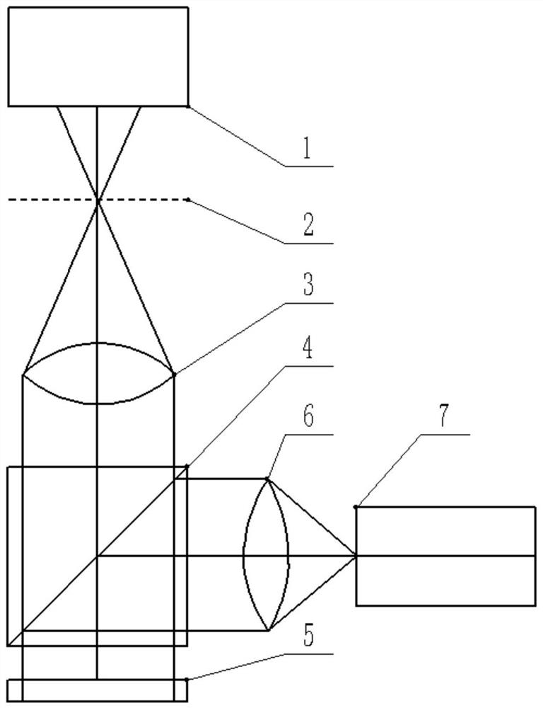
[0020] A self-focusing lens refractive index distribution detection system, such as figure 1 Shown: including laser 1, spatial filter 2, collimating objective lens 3, beam splitter 4, self-focusing lens 5, microscopic imaging system, image processing system; wherein, the microscopic imaging system includes microscopic objective lens 6 and camera 7; the laser light produced by the laser enters the spatial filter to form a divergent beam; the collimating objective lens collimates the divergent beam into a collimated beam; the collimated beam passes through the beam splitter and is incident on the self-focusing lens; The front surface of the self-focusing lens reflects the collimated beam to form a reference beam, and the rear surface of the self-focusing lens reflects to form a test beam. After the interference fringes generated by the reference beam and the test beam are reflected by the beam splitter, Incident to the microscopic imaging system, the microscopic objective lens o...

Embodiment 2

[0022] A method for detecting the refractive index distribution of the self-focusing lens based on the above-mentioned system for detecting the refractive index distribution of the self-focusing lens; the steps include:

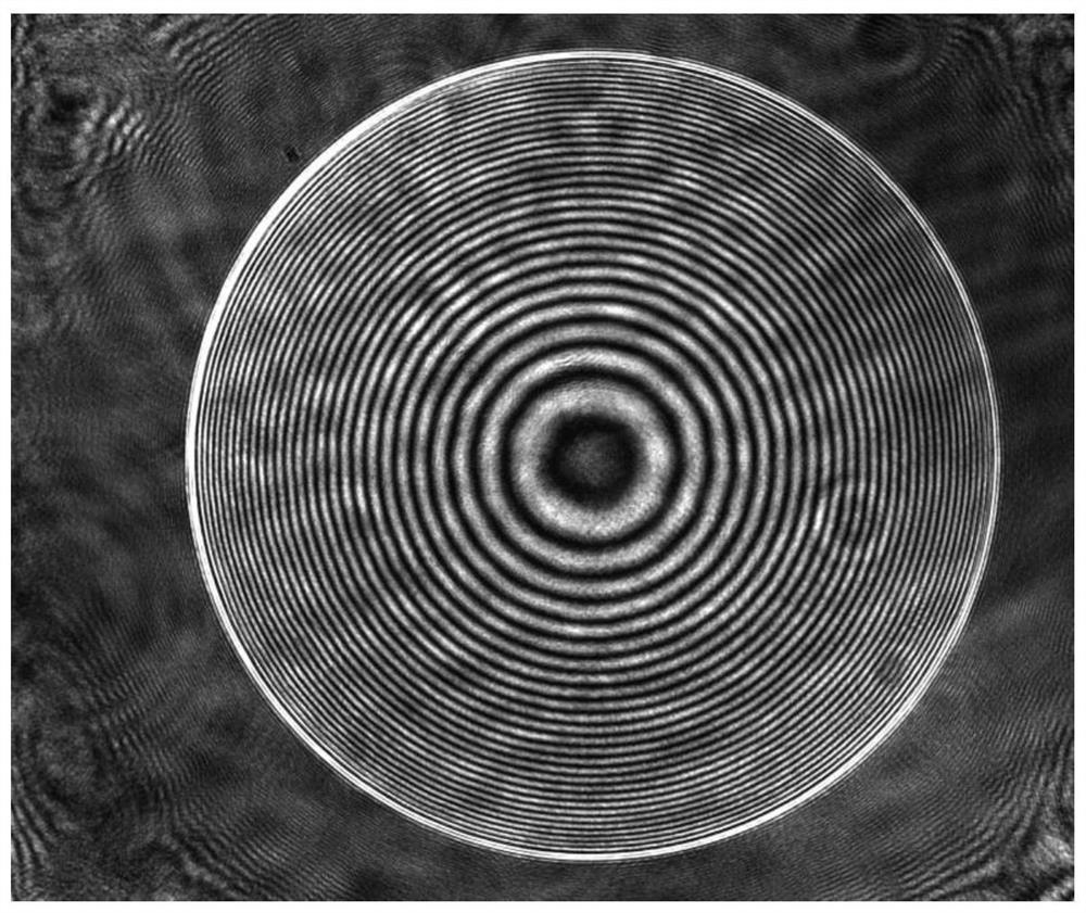
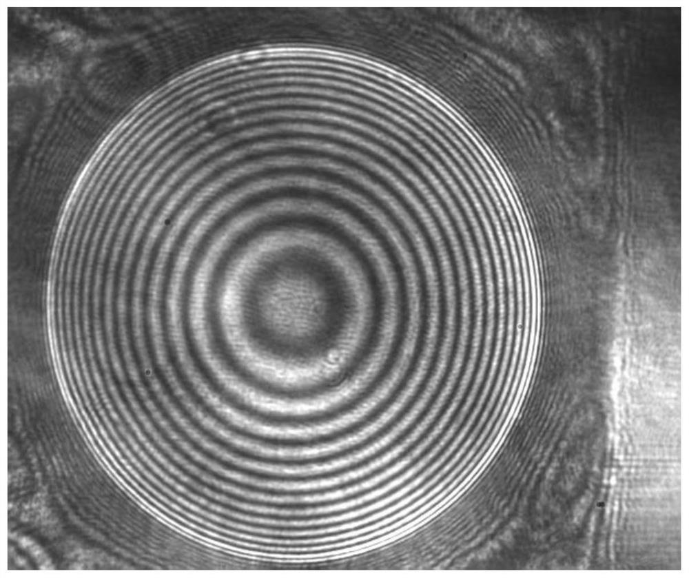
[0023] Place the self-focusing lens to be tested behind the beam splitter, turn on the laser to generate parallel light, so that the light is filtered by a spatial filter, and then after passing through the beam splitter, it is irradiated on the front and rear surfaces of the self-focusing lens, and after the self-focusing The front and rear surfaces of the lens are reflected into two beams of light, forming an interference light path, which is reflected to the microscopic imaging lens through the beam splitter, and finally the microscopic imaging lens images the interference fringes on the camera, and is resolved by the image processing system;

[0024] Move the imaging microscope system back and forth, so that the focal plane of the microscopic objective len...


PUM


Abstract

The invention relates to the technical field of optical measurement, and discloses a self-focusing lens refractive index distribution detection system and method in order to solve the problem of low refractive index detection precision caused by poor environmental interference resistance of an existing self-focusing lens refractive index distribution detection method. The front surface of a self-focusing lens reflects a collimated light beam to form a reference light beam, a test light beam is formed through reflection by the rear surface of the self-focusing lens, interference fringes generated by the reference light beam and the test light beam are reflected by a beam splitter and then enter a microscopic imaging system, an image processing system processes the interference fringes of the self-focusing lens collected by a camera, and the refractive index distribution of the self-focusing lens is obtained by analyzing the information of the interference fringes. According to the self-focusing lens refractive index distribution detection method based on the Fizeau interference principle, high-efficiency and high-precision self-focusing lens refractive index distribution detection is achieved, and meanwhile the Fizeau interferometer system has the advantages of being high in anti-interference capacity and small in size.

Description

technical field [0001] The invention relates to the technical field of optical measurement, in particular to a method for detecting the refractive index distribution of a self-focusing lens based on the principle of Fizeau interference. Background technique [0002] Self-focusing lens (GRIN lens, G-lens), also known as gradient index lens, is a cylindrical optical lens whose refractive index changes gradually along the radial direction, and has the functions of focusing and imaging. The self-focusing lens realizes the periodic propagation of light inside the lens by adjusting the radially graded refractive index, and the light modulation period can be adjusted by changing its length, thereby realizing the optical device with the same function as the lens. [0003] Due to the characteristics of end collimation, coupling and imaging, self-focusing lenses are widely used in micro-optical systems, medical optical instruments, optical copiers, fax machines, scanners and other equ...

Claims


Application Information

Patent Timeline
Patent Type & Authority Applications(China)
IPC IPC(8): G01M11/02
CPCG01M11/0228
Inventor 许峰林槟马锁冬孙鹏陈旭
Owner SUZHOU UNIV
Learn More