
Wind speed and wind direction measuring device based on CFD aerodynamic layout

A technology of wind speed, direction and measurement device, applied in measurement device, fluid velocity measurement, velocity/acceleration/impact measurement, etc., can solve problems such as affecting the accuracy of data measurement, not taking both appearance and function into consideration, etc.

Pending Publication Date: 2021-10-08
SEEED TECH
View PDF6 Cites 0 Cited by
  • Summary
  • Abstract
  • Description
  • Claims
  • Application Information

AI Technical Summary

Problems solved by technology

[0003] Most of the existing meteorological detection devices are single-element type and rough integration type, especially the appearance and function are not taken into consideration, such as the influence of air flow resistance caused by the shape, the influence on gas diffusion, and the influence on heat transfer
There are also old ultrasonic anemometers that are disturbed by strong winds on the sound wave reflection path, etc., which directly affects the data measurement accuracy.

Method used


Image

  • Wind speed and wind direction measuring device based on CFD aerodynamic layout
  • Wind speed and wind direction measuring device based on CFD aerodynamic layout
  • Wind speed and wind direction measuring device based on CFD aerodynamic layout

Examples


Embodiment Construction

[0038] The following will clearly and completely describe the technical solutions in the embodiments of the present invention with reference to the accompanying drawings in the embodiments of the present invention. Obviously, the described embodiments are only some, not all, embodiments of the present invention. Based on the embodiments of the present invention, all other embodiments obtained by those skilled in the art without creative efforts fall within the protection scope of the present invention.

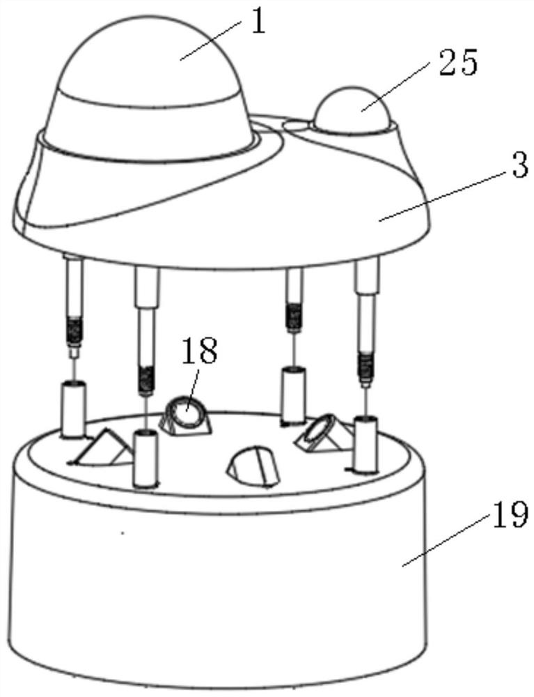
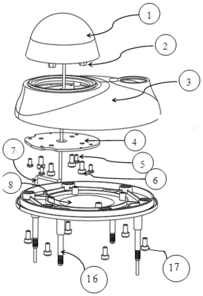
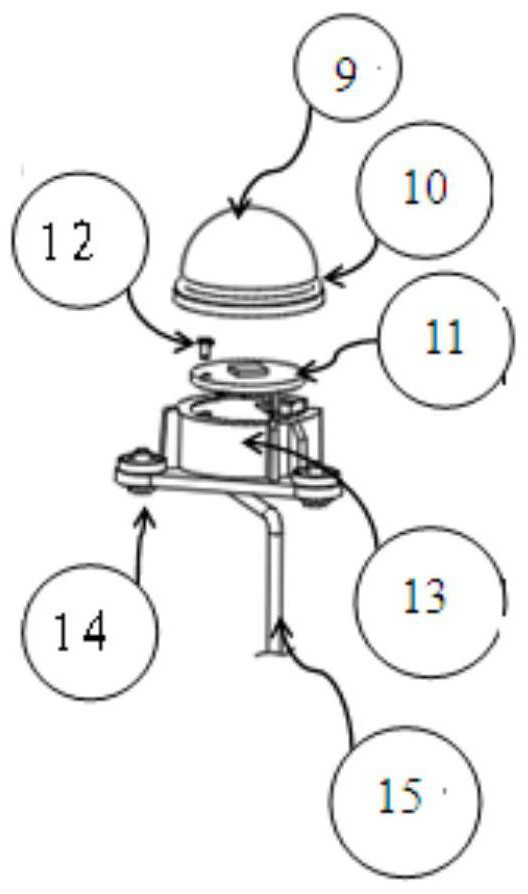
[0039] see Figure 1-4 The embodiment of the present invention provides a wind speed and direction measurement device based on CFD aerodynamic layout, including a top assembly and a main body assembly, wherein the top assembly includes a photoelectric rainfall module 1, a light intensity module 25, a top cover 3 and a reflector 8 ( not shown); if Figure 4 As shown, the top assembly is connected to the main body assembly through the hollow tooth bar 16, that is, the stainless...


PUM


Abstract

The invention discloses a wind speed and wind direction measuring device based on CFD aerodynamic layout; the wind speed and wind direction measuring device based on CFD aerodynamic layout comprises a top assembly and a main body assembly, wherein the top assembly comprises a photoelectric rainfall module, an illumination intensity module, a top cover and a reflecting plate; the main body assembly comprises an ultrasonic transducer, a main body shell and a main control board; the photoelectric rainfall module and the illumination intensity module are respectively fixed on the top cover, the reflecting plate is fixedly connected with the top cover, and the top assembly is connected with the main body assembly through a hollow threaded rod; the ultrasonic transducer is located on the main body assembly, the appearance form and the detection function are fused, the situation that sound wave energy receiving is affected due to the fact that a sound wave propagation path is blown to be deflected by strong wind is effectively prevented, and the measurement precision is improved.

Description

technical field [0001] The invention relates to the field of meteorological technology, in particular to a wind speed and wind direction measuring device based on CFD aerodynamic layout. Background technique [0002] At present, with the continuous deepening of industrial digitalization and intelligentization, the demand for meteorological data is increasingly strong for the fine development of agriculture, industry, construction, and animal husbandry. Such as smart farming, wind power, environmental monitoring, etc. In addition, global climate change factors are complex and multi-terminal, and accurate regional real-time meteorological monitoring, data analysis, and trend judgment are becoming more and more important. [0003] Most of the existing meteorological detection devices are single-element type and crudely integrated type, especially the appearance and function are not taken into consideration, such as the influence of air flow resistance caused by the form, the i...

Claims


Application Information

Patent Timeline
Patent Type & Authority Applications(China)
IPC IPC(8): G01P5/24G01P13/04G01W1/02
CPCG01P5/241G01P13/045G01W1/02Y02A90/10
Inventor 杨细军高超邵旭光杨波蒋宇
Owner SEEED TECH
Learn More