
Atmospheric monitoring method and system based on multi-rotor unmanned aerial vehicle

A multi-rotor UAV, atmospheric monitoring technology, applied in control/regulation systems, measuring devices, standard gas analyzers, etc., can solve the problem of low application efficiency, pollution early warning information, and difficulty in understanding the dynamic conditions of the atmospheric environment in a timely and comprehensive manner, etc. problem, to achieve the effect of light weight and simple operation

Pending Publication Date: 2021-10-08
李佳霖
View PDF0 Cites 0 Cited by
  • Summary
  • Abstract
  • Description
  • Claims
  • Application Information

AI Technical Summary

Problems solved by technology

[0004] The purpose of the present invention is to provide an atmospheric monitoring method and system based on a multi-rotor UAV, in order to improve the actual environment in the prior art due to the different actual observation areas, and the operating capability of a single UAV is limited by the endurance time, load weight, etc. Due to the limitation of environmental conditions and other factors, the application efficiency is low, and it is difficult to complete increasingly complex tasks, and it is difficult to timely and comprehensively understand the dynamic status of the atmospheric environment and issue pollution warning information.

Method used


Image

  • Atmospheric monitoring method and system based on multi-rotor unmanned aerial vehicle
  • Atmospheric monitoring method and system based on multi-rotor unmanned aerial vehicle
  • Atmospheric monitoring method and system based on multi-rotor unmanned aerial vehicle

Examples


Embodiment

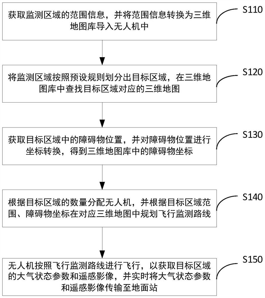
[0042] Please refer to figure 1 , figure 1 Shown is a flowchart of an atmospheric monitoring method based on a multi-rotor UAV provided in an embodiment of the present application. A kind of atmospheric monitoring method based on multi-rotor unmanned aerial vehicle, it comprises the steps:

[0043] S110: Obtain range information of the monitoring area, and convert the range information into a three-dimensional map library and import it into the drone;

[0044] Specifically, the monitoring area is determined according to the actual situation, the range information of the monitoring area is obtained according to the monitoring area, and the monitoring area is converted into a three-dimensional map library and stored in the UAV according to the range information of the monitoring area.

[0045] Exemplarily, the above-mentioned unmanned aerial vehicle may be a multi-rotor unmanned aerial vehicle. Compared with fixed-wing UAVs, multi-rotor UAVs can make up for the problems that ...


PUM


Abstract

The invention provides an atmospheric monitoring method and system based on a multi-rotor unmanned aerial vehicle, and relates to the technical field of atmospheric monitoring. The method comprises the following steps: converting range information into a three-dimensional map library and importing the three-dimensional map library into the unmanned aerial vehicle; dividing the monitoring area into a target area according to a preset rule, and searching a three-dimensional map corresponding to the target area in the three-dimensional map library; and performing coordinate conversion on the obstacle position to obtain an obstacle coordinate in the three-dimensional map library; distributing the unmanned aerial vehicles according to the number of the target areas, and planning a flight monitoring route in the corresponding three-dimensional map according to the target area range and the obstacle coordinates; and acquiring atmospheric state parameters and remote sensing images of the target area, and transmitting the atmospheric state parameters and the remote sensing images to a ground station in real time. The low application efficiency of the unmanned aerial vehicle due to the fact that the working capacity of the single unmanned aerial vehicle is limited by factors such as endurance time, load weight and environmental conditions is avoided, and therefore the atmospheric monitoring task is completed through the unmanned aerial vehicle so as to comprehensively know the dynamic condition of the atmospheric environment.

Description

technical field [0001] The invention relates to the technical field of atmospheric monitoring, in particular to an atmospheric monitoring method and system based on a multi-rotor unmanned aerial vehicle. Background technique [0002] In recent years, my country's industry has developed rapidly, and the air pollution caused by industrial development has become more and more serious. A variety of complex air pollutants produced by fuel combustion, industrial production, and transportation not only affect the air environment of the city, but also cause great damage to the health of urban residents, and even induce major physical diseases. Therefore, air pollution monitoring is becoming more and more important. [0003] Commonly used methods for measuring air pollutants include: meteorological observation towers, balloon observations, lidar, and manned fixed-wing aircraft. A large number of methods realize atmospheric observation by setting up observation stations on the groun...

Claims


Application Information

Patent Timeline
IPC IPC(8): G05D1/10G01N33/00
CPCG05D1/106G01N33/0006Y02A90/10
Inventor 李佳霖
Owner 李佳霖
Learn More