Alarm system for power transmission

An alarm system and power transmission technology, which is applied in the direction of alarms, electrical components, panel/switch station circuit devices, etc., can solve the problems of cabinet temperature rise, affecting the service life of equipment, and inability to perform high-temperature alarms, so as to avoid local Fever, strong pertinence, comprehensive and thorough monitoring effect

Active Publication Date: 2021-10-08
国网河南省电力公司鄢陵县供电公司
View PDF10 Cites 1 Cited by
  • Summary
  • Abstract
  • Description
  • Claims
  • Application Information

AI Technical Summary

Problems solved by technology

[0003] Among them, in the process of power generation, transmission, distribution and power conversion in the power system, high and low voltage switchgears are usually required to open and close, control and protect electrical equipment. The switchgear is mainly equipped with circuit breakers and isolating switches. , load switch, operating mechanism, transformer and various protection devices, which will generate heat during work, which will increase the internal temperature of the cabinet. The staff cannot find out that the temperature of the equipment is too high in time, nor can they take timely cooling measures, resulting in the failure of the equipment to work normally and affecting the service life of the equipment

Method used


Image

  • Alarm system for power transmission
  • Alarm system for power transmission
  • Alarm system for power transmission

Examples


Embodiment Construction

[0022] The technical solutions of the present invention will be further specifically described below through embodiments and in conjunction with the accompanying drawings.

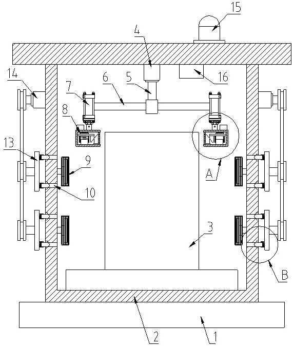
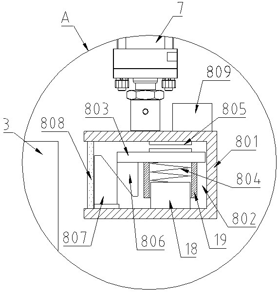
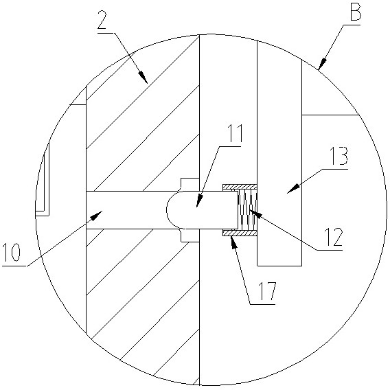
[0023] Such as figure 1 , figure 2 , image 3 As shown, an alarm system for power transmission includes a base 1, a box body 2, power equipment 3, a rotating motor 4, a rotating shaft 5, a connecting rod 6, a lifting device 7, a monitoring and early warning device 8, a cooling fan 9, and a ventilation hole 10 , Blocking block 11, compression spring 12, rotating plate 13, driving motor 14, warning light 15 and master controller 16.

[0024] Wherein, the base 1 is provided with a box body 2, the inside of the box body 2 is provided with an electric device 3, and the inner top wall of the box body 2 is provided with a rotating motor 4, and the output shaft of the rotating motor 4 is connected with Rotating shaft 5, the bottom end of the rotating shaft 5 is provided with a horizontal connecting rod 6, the ...


PUM


Abstract

The invention discloses an alarm system for power transmission. A box body is arranged on a base, power equipment is arranged in the box body, a rotating motor is arranged on the top wall in the box body, an output shaft of the rotating motor is connected with a rotating shaft, a horizontal connecting rod is arranged at the bottom end of the rotating shaft, and a lifting device is arranged at one end, away from the rotating shaft, of the connecting rod; a monitoring and early warning device arranged at the output end of the lifting device, a cooling fan is arranged on the inner side wall of the box body, ventilation holes are formed in the outer side wall of the box body, plugging blocks are arranged on the outer sides of the ventilation holes, the outer ends of the plugging blocks are connected with a rotating plate through compression springs, and the outer side of the rotating plate is connected with a driving motor through a belt and a belt wheel; and a main controller and an alarm lamp are further arranged at the top of the box body, and the main controller is electrically connected with the rotating motor, the lifting device, the monitoring and early warning device, the cooling fan, the driving motor and the alarm lamp in a controlling mode. The system has the advantages of real-time monitoring, timely early warning, heat dissipation and cooling, and prolonging of the service life of equipment.

Description

technical field [0001] The invention belongs to the technical field of electric power transmission, and in particular relates to an alarm system for electric power transmission. Background technique [0002] In recent years, with the rapid development of the power industry, the power system is developing towards high voltage and large capacitance. The relationship between electric energy and the development of the national economy and people's production and life is inseparable. Cause loss, so when transmitting, the electric energy is first transmitted from the power plant to the step-up substation, the voltage is increased through the substation, the current is reduced to reduce heat loss, and then transmitted through the high-voltage transmission line, and then through the step-down In the substation, the voltage is reduced to the voltage required by the target electrical appliance, and then transmitted to the user through the low-voltage distribution line. [0003] Among...

Claims


Application Information

Patent Timeline
Patent Type & Authority Applications(China)
IPC IPC(8): H02B1/46H02B1/48H02B1/56H02B1/24H02B1/28H02B1/50G08B21/18
CPCH02B1/46H02B1/48H02B1/565H02B1/24H02B1/28H02B1/50G08B21/18
Inventor 王春风李树丽古佳明张誉文杨麒
Owner 国网河南省电力公司鄢陵县供电公司
Why Eureka
Try Eureka