Supercharge Your Innovation With Domain-Expert AI Agents!

Buffer device and power distribution equipment

A buffer device and power distribution equipment technology, which is applied in the direction of anti-seismic equipment, electrical components, substation/switch layout details, etc., can solve the problems of insufficient overall support of the foam rubber pad, limited buffering and shock absorption effect, and large deformation range. To achieve good cushioning and shock absorption effect, the best cushioning and shock absorption effect, and the effect of convenient connection

Pending Publication Date: 2021-10-08
上海中科益海船舶科技有限公司
View PDF0 Cites 0 Cited by
  • Summary
  • Abstract
  • Description
  • Claims
  • Application Information

AI Technical Summary

Problems solved by technology

[0006] However, although the aforementioned steel wire rope shock absorber has a large deformation range and high supporting force, it has the disadvantages of large volume and heavy weight. In particular, in order to constrain and fix the multi-turn steel wire rope, it is necessary to use a larger metal structure, which further increases the In order to occupy space and weight; at the same time, in order to ensure that the steel wire rope shock absorber is not easy to corrode, it is necessary to use precious metal materials such as stainless steel or brass to make the steel wire rope shock absorber, resulting in higher production costs
[0007] Among the aforementioned rubber pads, the deformation range of the solid rubber pad is relatively small, and the cushioning and shock absorption effect is limited; the foamed rubber pad is full of air bubbles, and the cut surface is honeycomb. Compared with the solid rubber pad, the deformation range is larger, and the cushioning and shock absorption effect is comparable. It is better than the solid rubber pad, but because of the large deformation range, the overall support of the foam rubber pad is insufficient. When the weight of the power distribution equipment is heavy, it is very easy to cause the foam rubber pad to be completely compressed and unable to rebound. , at this time, the foam rubber pad will not be able to play a shock-absorbing buffer effect

Method used


Image

  • Buffer device and power distribution equipment
  • Buffer device and power distribution equipment
  • Buffer device and power distribution equipment

Examples


Embodiment Construction

[0028] The following will clearly and completely describe the technical solutions in the embodiments of the present invention with reference to the accompanying drawings in the embodiments of the present invention. Obviously, the described embodiments are only part of the embodiments of the present invention, not all of them. Based on the embodiments of the present invention, all other embodiments obtained by persons of ordinary skill in the art without making creative efforts belong to the protection scope of the present invention.

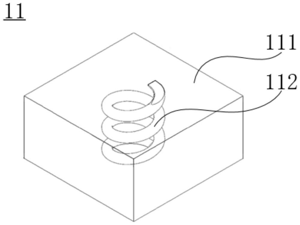
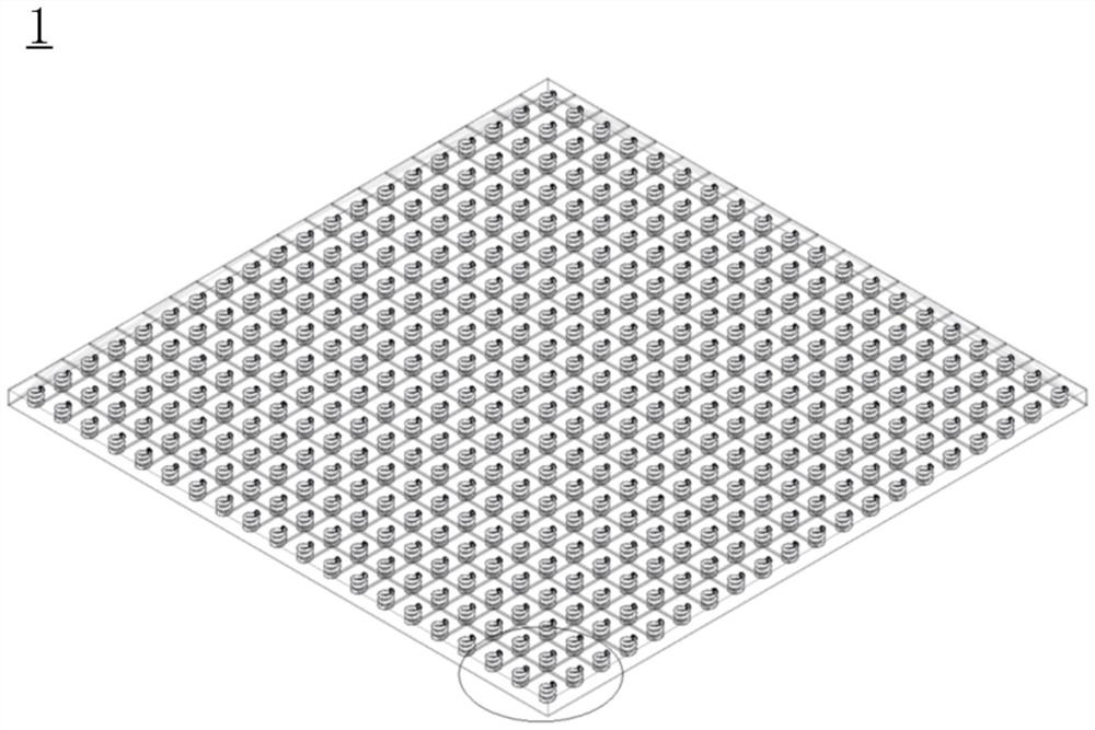
[0029] see Figure 1 to Figure 5 As shown, the present embodiment provides a buffer device 1, including at least one buffer unit 11, each of which includes a first elastic structure 111 and a second elastic structure 112, and the first elastic structure 111 is located in the The buffering direction exceeds the second elastic structure 112 , that is, the second elastic structure 112 does not exceed the first elastic structure 111 in the buffering ...


PUM


Abstract

The invention provides a buffer device and power distribution equipment. The buffer device comprises at least one buffer unit, each buffer unit comprises a first elastic structure and a second elastic structure, and the second elastic structure does not exceed the first elastic structure in the buffer direction of the buffer device; and in the buffering direction of the buffer device, the maximum elastic deformation of the first elastic structure is larger than that of the second elastic structure, and the elastic coefficient of the first elastic structure is smaller than that of the second elastic structure. In the buffer device provided by the invention, the first elastic structure enables the buffer device to have a larger elastic deformation quantity, the second elastic structure enables the buffer device to have a larger elastic supporting force, and the buffer device has the better maximum elastic deformation quantity and the better supporting strength at the same time; and therefore, a better buffering and damping effect can be realized.

Description

technical field [0001] The invention relates to the technical field of electrical equipment, in particular to a buffer device and power distribution equipment. Background technique [0002] The power distribution equipment usually includes a housing and a power distribution component. The housing (such as a power distribution cabinet, a power distribution box, or a power distribution panel, etc.) is arranged outside the power distribution component, and the power distribution component is accommodated In the housing, the housing can protect and carry the power distribution components inside it. At the same time, in order to reduce the impact of external shocks and vibrations on the housing and the power distribution components inside, shock absorbing and buffering devices are usually provided at the connection between the housing and the main structure (such as the foundation of the ship's warehouse). [0003] For example, the inventor of the present application is aware of...

Claims


Application Information

Patent Timeline
Patent Type & Authority Applications(China)
IPC IPC(8): H02B1/54H02B1/50
CPCH02B1/54H02B1/50
Inventor 张金涛陈庆培王阳生
Owner 上海中科益海船舶科技有限公司
Features
  • R&D
  • Intellectual Property
  • Life Sciences
  • Materials
  • Tech Scout
  • Unparalleled Data Quality
  • Higher Quality Content
  • 60% Fewer Hallucinations
Learn More