
Indexable drill, cutting insert and drill main body

A technology of indexing inserts and cutting inserts, used in drilling/drilling equipment, repair drills, twist drills, etc., can solve the problems of wear on the torque bearing surface and torque transmission surface, shorten the life of the drill bit, etc., to prevent wear and tear. , The effect of stable drilling and scratch prevention

Pending Publication Date: 2021-10-08
MITSUBISHI MATERIALS CORP
View PDF8 Cites 0 Cited by
  • Summary
  • Abstract
  • Description
  • Claims
  • Application Information

AI Technical Summary

Problems solved by technology

[0005] However, in the indexable insert type drill described in Patent Document 1, the torque receiving surface of the cutting insert is adjacent to and intersects with the front end flank, and the contact between the torque receiving surface and the torque transmitting surface of the drill body is The joint is exposed on the front end of the indexable insert drill
Therefore, especially in the case of wet cutting in which drilling is performed while supplying coolant, the fine chips generated by cutting tend to become sludge together with the coolant and enter the torque receiving surface and the The contact part of the torque transmission surface may wear the torque receiving surface and the torque transmission surface due to the sludge, which may shorten the life of the drill bit

Method used


Image

  • Indexable drill, cutting insert and drill main body
  • Indexable drill, cutting insert and drill main body
  • Indexable drill, cutting insert and drill main body

Examples


Embodiment Construction

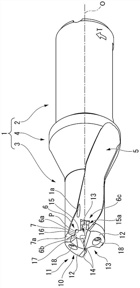
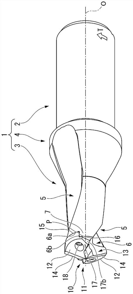
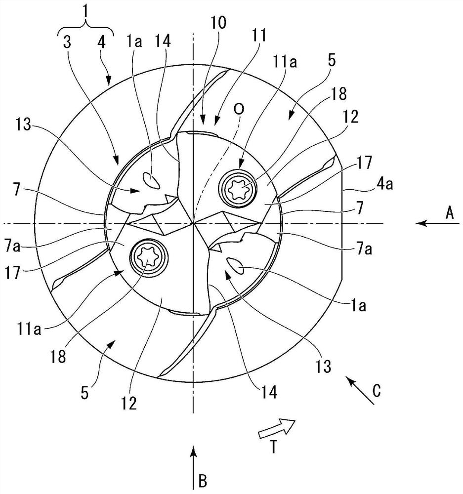
[0056] Figure 1 to Figure 6 The first embodiment of the indexable insert drill in the present invention is shown, Figure 7 An exploded view of the indexable insert drill according to the first embodiment is shown. Figure 8 and Figure 9 A first embodiment showing the drill main body used in the indexable insert drill according to the first embodiment, Figure 10 ~ Figure 14 A first embodiment of a cutting insert detachably attached to the drill body is shown.

[0057] The drill body 1 is formed of a metal material such as steel into a multi-stage cylindrical shape centered on the axis O. As shown in FIG. The rear end of the drill body 1 (in figure 1 , figure 2 , Figure 4 ~ Figure 7 and Figure 9 The middle is the right side part) is the large diameter handle 2, the front end (in figure 1 , figure 2 , Figure 4 ~ Figure 7 and Figure 9 The left part in the middle) is the cutting edge portion 3 of the insert body 11 to which the cutting insert 10 is detachably a...


PUM


Abstract

In this indexable drill, a cutting insert (10) formed having a cutting blade (14) can be detachably attached to an insert attachment seat (6) of a drill main body (1). The insert attachment seat (6) is formed having a bottom surface (6a) which faces the tip of the drill main body (1), and a sidewall (6b) which extends towards the tip and faces the drill rotation direction (T). The cutting insert (10) is formed having a seated surface (15), which faces the back end of the drill main body (1) and is seated on the bottom surface (6a), a contact surface (16), which faces opposite of the drill rotation direction (T) and contacts the side surface (6b), a protrusion (17), which protrudes opposite of the drill rotation direction (T) on the tip side of the contact surface (16), and an attachment hole which passes from a tip flank surface (12) towards the seated surface (15).

Description

technical field [0001] The invention relates to an indexable insert drill, a cutting insert and a drill body of the indexable insert drill. In this indexable insert drill, an insert mounting seat is formed at the front end of a drill body that rotates around an axis, and a cutting insert is detachably attached to the insert mounting seat. The cutting insert is detachably attached to the insert mounting seat of this type of insertable drill. [0002] This application claims priority based on Patent Application No. 2019-50081 filed in Japan on March 18, 2019 and Patent Application No. 2020-25571 filed in Japan on February 18, 2020, and uses these contents here. Background technique [0003] For example, in the indexable insert type drill described in Patent Document 1, a split surface extending perpendicular to the axis and a torque transmission surface adjacent to the split surface are formed on the insert mounting seat of the drill body. The insert is formed with a split s...

Claims


Application Information

Patent Timeline
Patent Type & Authority Applications(China)
IPC IPC(8): B23B51/00B23B51/02
CPCB23B51/02B23B2251/48B23B2251/40B23B2251/20
Inventor 臼井正洋
Owner MITSUBISHI MATERIALS CORP
Learn More