Bed control method

A main control and humidity control technology, applied in the field of bed control, can solve problems such as hot air or cold air cannot be supplied

Pending Publication Date: 2021-10-12
LG ELECTRONICS INC
View PDF12 Cites 0 Cited by
  • Summary
  • Abstract
  • Description
  • Claims
  • Application Information

AI Technical Summary

Problems solved by technology

[0018] However, in the case of Patent Document 3, in a bed structure in which a part of the mattress is inclined, there is still a disadvantage that hot air or cold air supplied from the blower cannot be smoothly supplied to the mattress side.

Method used


Image

  • Bed control method
  • Bed control method
  • Bed control method

Examples


Embodiment Construction

[0117] Hereinafter, a pad strength control unit and a bed including the pad strength control unit according to an embodiment of the present invention will be described in detail with reference to the drawings.

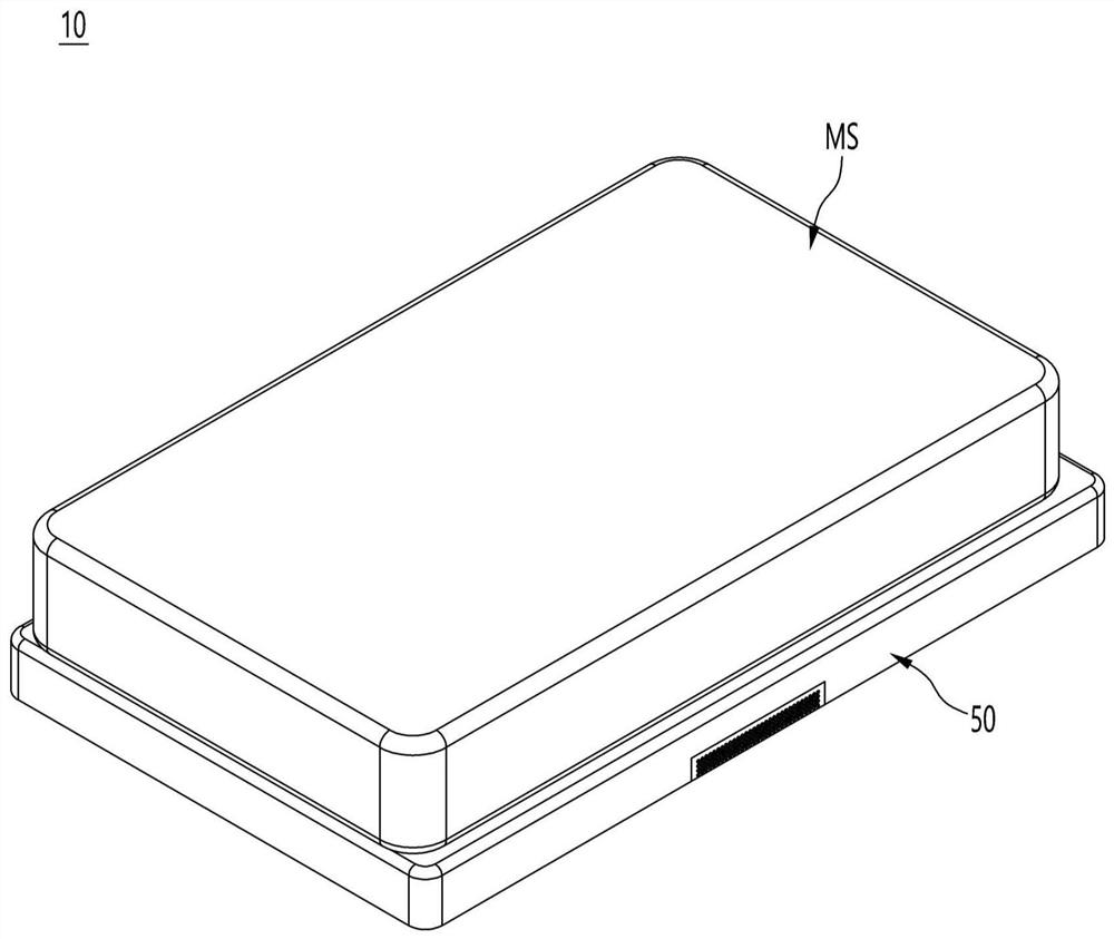
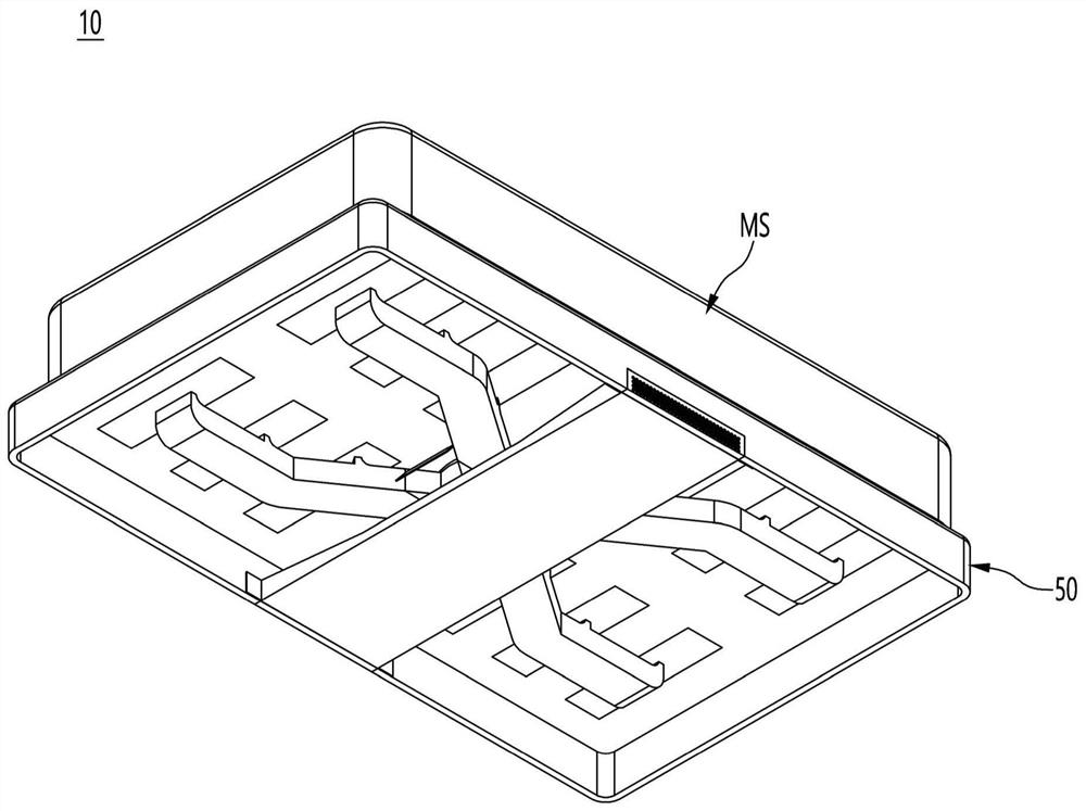
[0118] figure 1 is a perspective view of the bed of the first embodiment of the present invention, figure 2 It is a bottom perspective view of the bed of the first embodiment of the present invention.

[0119] refer to figure 1 and figure 2, the bed 10 of the first embodiment of the present invention may include: a mattress set MS; and a drying module 50 on which the mattress set MS is placed.

[0120] The mattress set MS is detachable and replaceable from the drying module 50, and at least a part of the mattress set MS can be tilted.

[0121] Hereinafter, the structures of the mattress set MS and the drying module 50 and the functions of the components will be described in detail with reference to the drawings.

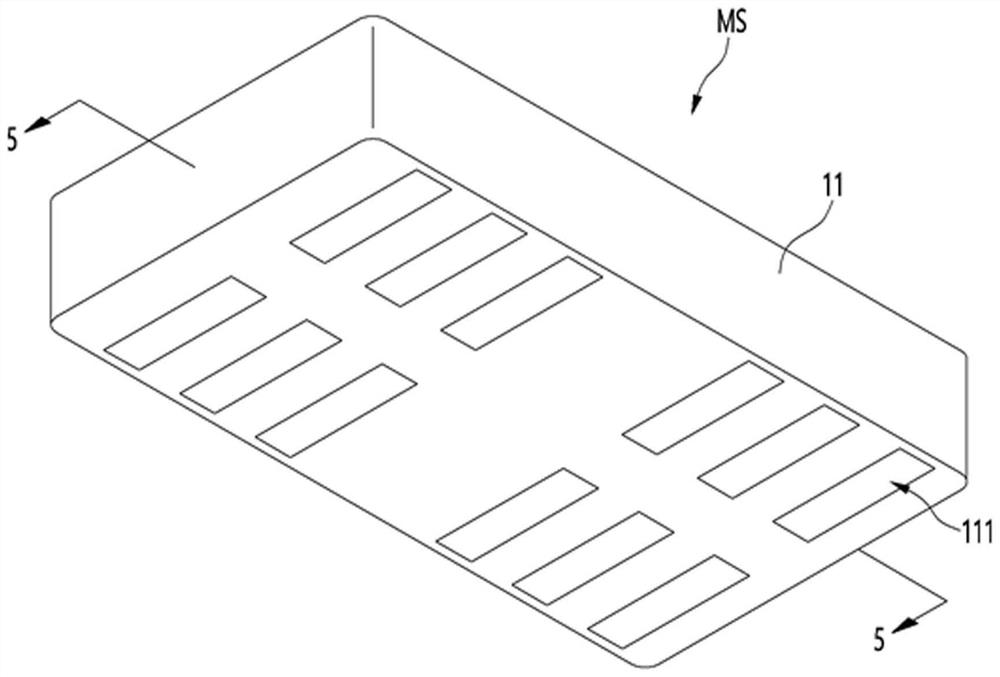
[0122] image 3 is a bottom perspective view o...


PUM


Abstract

A bed control method is provided. The bed control method can include a step of switching on a power supply of a bed; a step of selecting automatic dehumidification; a step of scanning current humidity values of different regions of a humidity sensing thin plate; a step of sending the current humidity values of different regions to a main controller; a step of determining, by the main controller, whether an over-wet region the humidity value of which deviates from a set range exists or not, and if yes, starting a heater and a blowing fan for a set period of time to perform dehumidification.

Description

technical field [0001] The present invention relates to bed control methods. Background technique [0002] Generally speaking, mattresses that function as a bed pad include spring mattresses, sponge mattresses, memory foam mattresses, etc., and spring mattresses are the most widely used. [0003] The spring mattresses of the prior art are formed with a single mattress member in which a plurality of helical compression springs are intricately intertwined, or with a structure in which a plurality of pocket spring modules are arranged. [0004] In the case of a mattress in which a plurality of helical compression springs are intricately entangled, when the user is lying down, the vibration generated by the elastic force of the springs is directly transmitted to others, causing discomfort to others. [0005] If it is a mattress including a pocket spring module, although it has the advantage of relatively reducing the amount of vibration transmitted to others, these mattresses i...

Claims


Application Information

Patent Timeline
Patent Type & Authority Applications(China)
IPC IPC(8): A47C21/00A47C21/04A47C31/00F26B21/00F26B25/00
CPCA47C31/00A47C21/00A47C21/044A47C21/048F26B25/00F26B21/001A47C31/008A47C23/002A47C20/041A47C23/0435A47C27/061A47C21/003
Inventor 金铉起吴旼奎李得远金容南金大雄安城右朱懃虎卢良焕
Owner LG ELECTRONICS INC
Why Eureka
Try Eureka