
Low-concentration gas efficient mixing device and method

A low-concentration gas, high-efficiency technology, applied in the field of pneumatic blending, can solve the problems of low blending effect, low blending pressure loss, and inability to effectively adjust the blending strength of the blending device, so as to reduce the length of the mixing section and reduce the Investment cost, the effect of improving the installation space environment

Pending Publication Date: 2021-10-12
ZHEJIANG YIYANG ENERGY TECH
View PDF3 Cites 0 Cited by
  • Summary
  • Abstract
  • Description
  • Claims
  • Application Information

AI Technical Summary

Problems solved by technology

The swirl vane blending mentioned in the patented technology "Swirling Flow Blending Device" (CN105032225A) is a method that can achieve better blending uniformity, but this blending method cannot effectively adjust the blending of the blending device according to demand. mixed strength
In the patented technology "A Coal Mine Gas Blending Device" (CN106237880A), the annular tube is used to form gases with different airflow directions for blending. This method has a simple structure and low blending pressure loss, but the blending effect of this method is Obviously lower than the blending method in the patented technology (CN105032225A)

Method used


Image

  • Low-concentration gas efficient mixing device and method
  • Low-concentration gas efficient mixing device and method
  • Low-concentration gas efficient mixing device and method

Examples


Embodiment

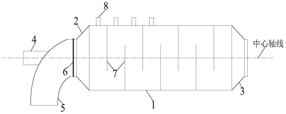
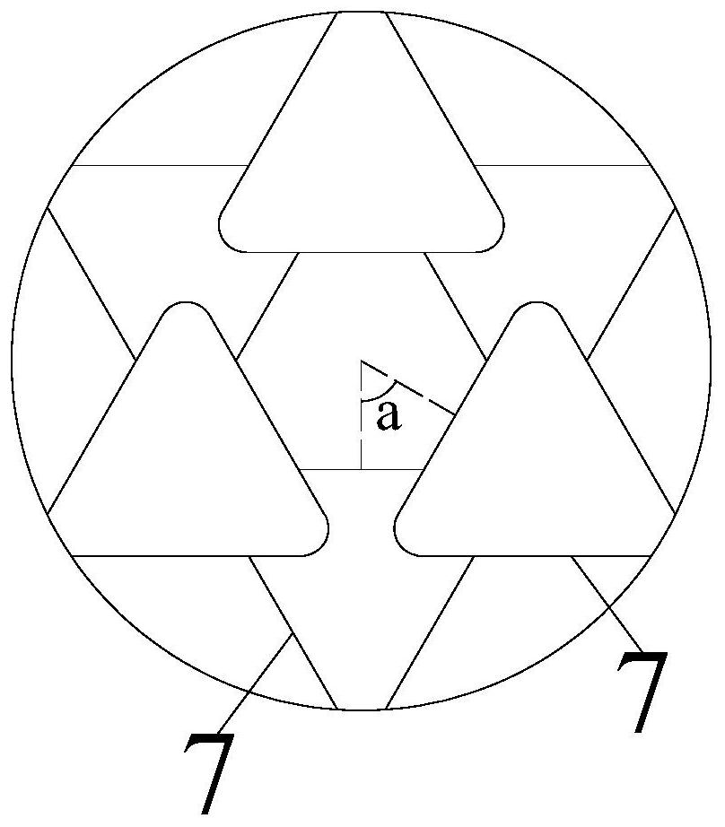
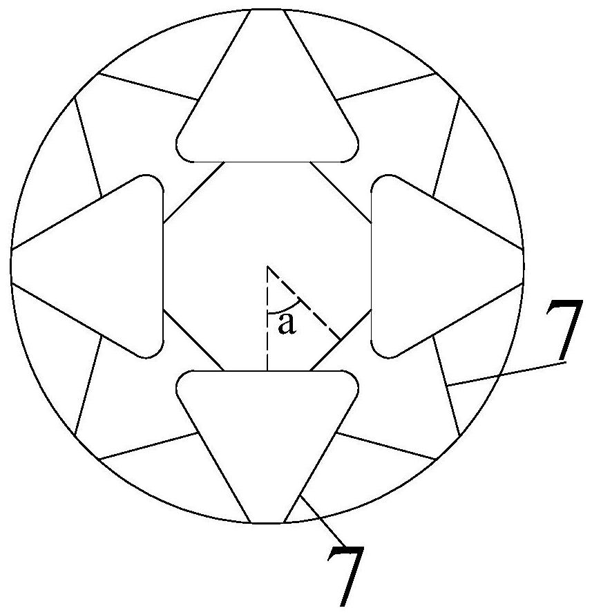
[0029] see figure 1 , in this embodiment, a low-concentration gas high-efficiency blending device includes: a mixing chamber 1, an air inlet pipe mouth 2, an air outlet pipe mouth 3, a low-concentration gas air inlet pipe 4, an air inlet pipe 5, a flange 6, a disturber Flow device 7, turbulence inlet port 8 and spoiler 9, the mixing chamber 1 is a cylindrical cavity body structure, the inlet end of the mixing chamber 1 is connected with an inlet nozzle 2, and the inlet nozzle 2 flows along the gas The direction is the expansion pipe, the outlet end of the mixing chamber 1 is connected with the outlet pipe port 3, and the air outlet pipe port 3 is a contraction pipe along the gas flow direction, and the air inlet pipe 5 is connected with the inlet end of the air inlet pipe port 2 through the flange 6, And the air intake direction of the air intake pipe 5 is perpendicular to the central axis of the mixing chamber 1, and the air intake pipe 5 is also connected to the low-concentr...


PUM


Abstract

The invention discloses a low-concentration gas efficient mixing device and method. The low-concentration gas efficient mixing device mainly comprises a mixing cavity, a gas inlet pipe opening, a gas outlet pipe opening, a low-concentration gas inlet pipe, an air inlet pipe, a flange, turbulent flow equipment, a turbulent flow gas inlet end and a turbulent flow device, wherein the turbulent flow equipment and the turbulent flow device are arranged inside the mixing cavity; the turbulent flow gas inlet end is arranged at the outer side of the front half section of the mixing cavity; air and low-concentration gas enter the mixing cavity through the gas inlet pipe opening to be mixed; the mixing intensity is enhanced by using the turbulent flow equipment and the turbulent flow device inside the mixing cavity; and good mixing uniformity is achieved; meanwhile, the mixing intensity of the mixing device is regulated through the regulation of the turbulent flow gas inlet, so that the goal of precisely controlling the mixing uniformity of the mixed gas is achieved. The mixing intensity of the mixing device is enhanced; the mixing time is greatly shortened; the length of the mixing section is reduced, so that the investment cost of the mixing device is reduced; the installation space environment of the mixing device is also improved; and the obvious popularization values are realized.

Description

technical field [0001] The invention belongs to the technical field of pneumatic mixing, and in particular relates to a low-concentration gas high-efficiency mixing device and method. Background technique [0002] Due to the design of the production process of coal mines, coal mines in my country usually produce gas with different gas concentrations during the production process. Among them, high-concentration gas can be used directly, while low-concentration gas, especially ventilation gas, due to the low gas methane concentration ( <0.3%) and large fluctuations, which is not conducive to the stable operation of the oxidation device. For example, the most important and promising technology for effective treatment of ultra-low-concentration and large-volume coal mine ventilation gas is regenerative oxidation technology. Before performing regenerative oxidation, it is necessary to mix low-concentration gas with air. Form the gas mixture with the gas concentration required ...

Claims


Application Information

Patent Timeline
Patent Type & Authority Applications(China)
IPC IPC(8): E21F7/00E21F17/00F04F5/16F04F5/44
CPCE21F7/00E21F17/00F04F5/16F04F5/44
Inventor 何勇陈菁吴宇刘锋川徐家坤豆文举于涛
Owner ZHEJIANG YIYANG ENERGY TECH
Learn More