Coupled double-fluidized-bed low-nitrogen combustion device and method
A low-nitrogen combustion and dual fluidized bed technology, applied in fluidized bed combustion equipment, combustion methods, fluidized bed boilers, etc., can solve the complex structure of the new furnace, high investment, operation and maintenance costs, ammonia escape and other problems , to achieve the effect of ensuring combustion efficiency and energy conversion efficiency, reducing denitrification investment and operating costs, and reducing the original NOx emission concentration
- Summary
- Abstract
- Description
- Claims
- Application Information
AI Technical Summary
Problems solved by technology
Method used
Image
Examples
Embodiment 1
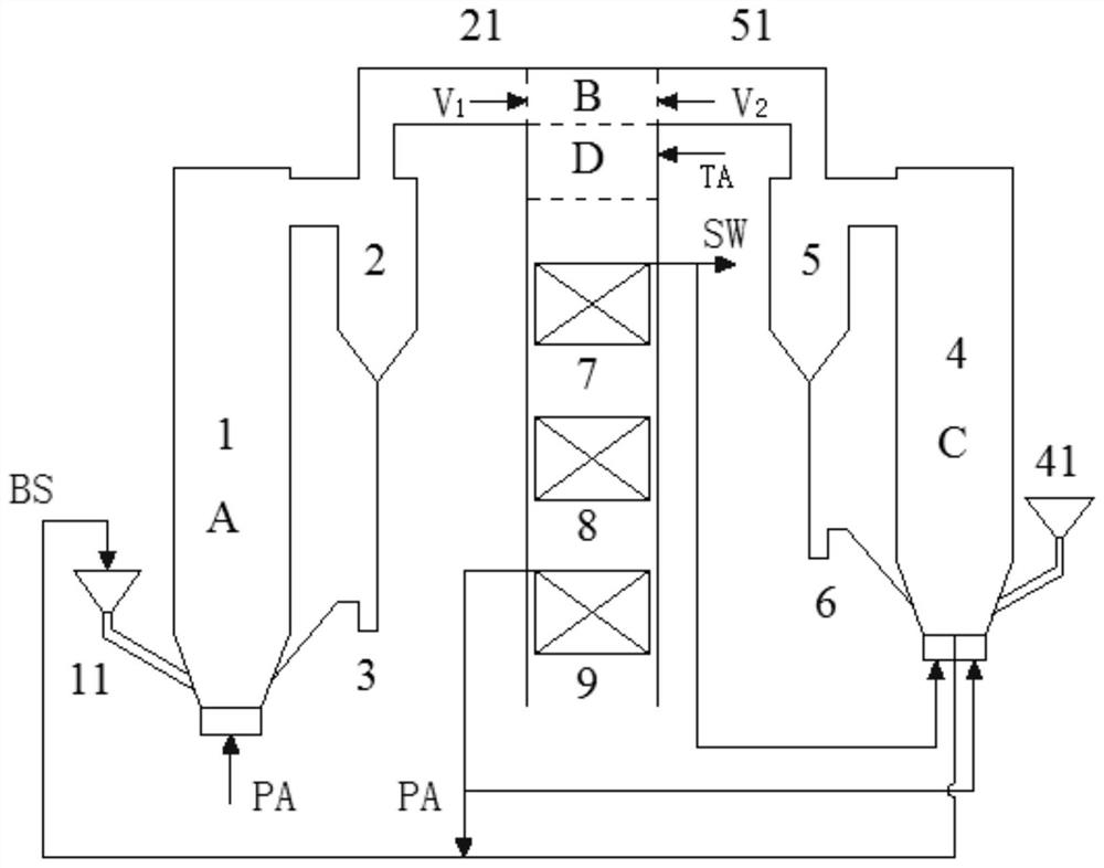
[0039] A coupled double fluidized bed low nitrogen combustion device, such as figure 1 As shown, it includes a combustion unit, a gasification unit, a reburning denitrification burnout zone and a tail flue; the combustion unit and the gasification unit are set independently of each other; The outlet of the reburning and denitrification burnout zone is connected to the outlet of the tail flue; the middle and lower side wall of the reburning and denitrification burnout zone is provided with at least one post-combustion air nozzle.
[0040] Wherein the combustion unit comprises a combustion chamber 1 (circulating fluidized bed furnace), the first cyclone separator 2 and the first return device 3; the gasification unit comprises a gasification chamber 4, the second cyclone separator 5 and the second single-side return Feeder 6; the lower front wall of the combustion chamber 1 is provided with the first coal feeder 11 feeding port, the lower rear wall is provided with the material re...
specific Embodiment 2
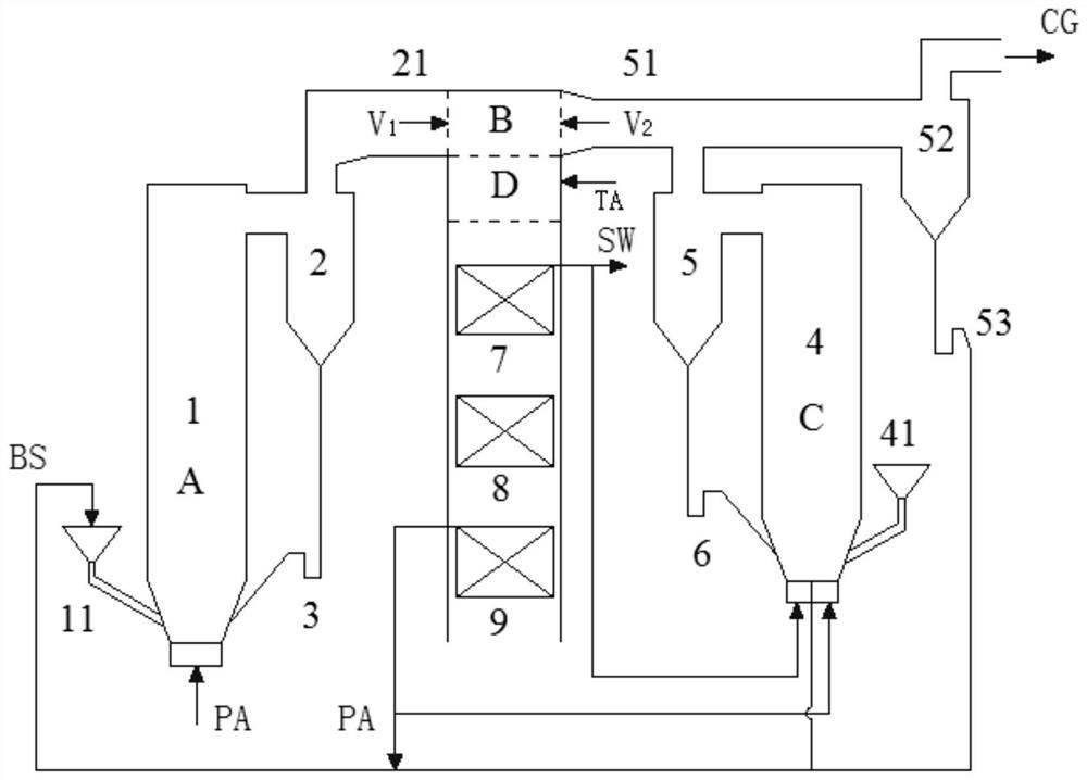
[0062] The difference between specific embodiment 2 and specific embodiment 1 is that it also includes a third cyclone separator 52 and a third return device 53; as image 3 As shown, the gas phase outlet at the top of the second cyclone separator 5 communicates with the inlet of the second flue 51 and the inlet of the third cyclone separator 52 respectively; The inlet is connected, and the gas phase outlet on the upper part of the third cyclone separator 52 is connected to the gas pipeline at the tail;
specific Embodiment 3
[0064] The difference between the specific embodiment 3 and the specific embodiment 1 is that the gasification chamber 4 is replaced with the pyrolysis chamber 4 ', and the second single-side feeder 6 is replaced with the second double-side feeder 6 ', as Figure 4 shown.
[0065] Part of the semi-coke SC coming out of the second double-side returner 6' returns to the pyrolysis zone C1 of the pyrolysis chamber 4' to continue to participate in the pyrolysis reaction, and the other part of the semi-coke SC coming out of the second double-side returner 6' Under the action of the primary hot air PA from the air preheater 9, the SC returns to the middle and lower part of the combustion chamber 1 through the circular semi-coke feed port 12 as reburning fuel, and performs the first-stage denitrification reduction reaction on the NOx generated by bottom combustion. The flue gas from the first cyclone separator 2 and the pyrolysis gas from the second cyclone separator 5 are intensively...
PUM
 Abstract
Description
Claims
Application Information
 - R&D
- Intellectual Property
- Life Sciences
- Materials
- Tech Scout
- Unparalleled Data Quality
- Higher Quality Content
- 60% Fewer Hallucinations
Browse by: Latest US Patents, China's latest patents, Technical Efficacy Thesaurus, Application Domain, Technology Topic, Popular Technical Reports.
© 2025 PatSnap. All rights reserved.Legal|Privacy policy|Modern Slavery Act Transparency Statement|Sitemap|About US| Contact US: help@patsnap.com


