Hub bearing with spline structure

A wheel hub bearing and spline technology, applied in the field of wheel hub bearings, can solve the problems of reducing the use effect of the overall structure, difficulty in replenishing oil for the hub bearing, and external impurities that easily affect the overall structure, etc.

Active Publication Date: 2021-10-12
C&U CO LTD +1
View PDF8 Cites 0 Cited by
  • Summary
  • Abstract
  • Description
  • Claims
  • Application Information

AI Technical Summary

Problems solved by technology

When the traditional hub bearing is in use, due to the continuous vibration of the working environment and the harsh working environment, external impurities are easy to affect the overall structure and easily enter the interior of the bearing, which seriously affects the use effect of the overall structure. At the same time, during the use of the overall bearing, A large amount of lubricating grease is required to maintain the smoothness of the overall work. At present, it is difficult to replenish oil for the hub bearing, and it needs to be disassembled and replaced as a whole. The maintenance cost is high and the use effect of the overall structure is reduced.

Method used


Image

  • Hub bearing with spline structure
  • Hub bearing with spline structure
  • Hub bearing with spline structure

Examples


Embodiment Construction

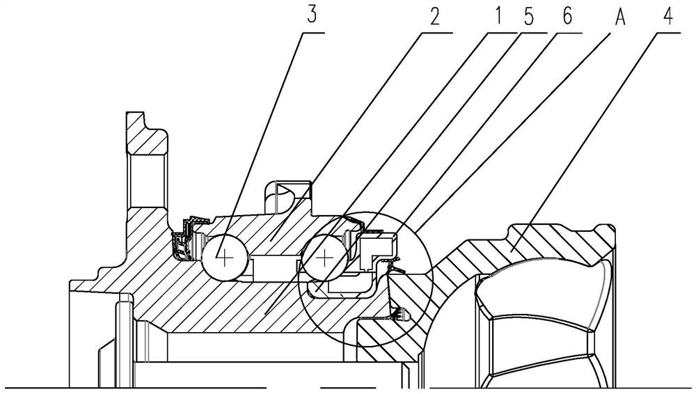
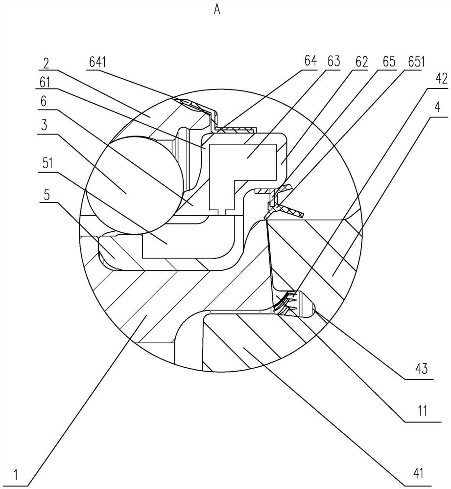
[0023] The present invention has an embodiment of a hub bearing having a spline structure, for example Figure 1 to 3 As shown: including the rotary connector 4, the flange inner ring 1, the flange outer ring 2 and the inner ring, the flange inner ring 1 and the flange outer ring 2 form a first roller, the connection A first roller is provided on the outer wall of the inner ring, and the flange outer ring 2 is provided with a second raceway corresponding to the first raceway, the first raceway and the second roller form a second roller, The first roller 3 is provided in the first roller 3, and a cartridge is formed on the flange inner ring 1, and the connecting inner ring split is provided with a first circle body 5 and a second. A plurality of guide grooves and guide blocks are disposed between the first circular body 5 and the second loop bodies 6, the guide groove and the guide block inserted to form a first circle 5 and the second loop 6 The fixed connection is disposed in the ...


PUM


Abstract

The invention discloses a hub bearing with a spline structure. The hub bearing with the spline structure comprises a rotary connector, a flange inner ring, a flange outer ring and a connecting inner ring, a first rolling groove is formed between the flange inner ring and the flange outer ring, a second rolling groove is formed between the connecting inner ring and the flange outer ring, steel balls are arranged in the first rolling groove and the second rolling groove, a clamping groove is formed in the flange inner ring, the connecting inner ring is arranged in a split mode to form a first ring body and a second ring body, a plurality of guide grooves and guide blocks are arranged between the first ring body and the second ring body, the guide grooves and the guide blocks are formed in an inserted fit mode, the first ring body is clamped in the clamping groove, a first sliding way and a second sliding way are arranged at the positions, corresponding to the steel balls, of the first ring body and the second ring body respectively, the second ring body extends towards the flange outer ring to form a shielding table, and the second ring body extends towards the rotary connector to form a shielding table. The structure is reasonable, a good sealing effect is achieved, disassembly for oil supplementing is convenient, and the using effect of the whole structure is improved.

Description

Technical field [0001] The present invention relates to the field of hub bearings. Background technique [0002] The wheel bearing of the drive wheel is typically used in pairs, and the outer spline is connected to the vehicle drive element, that is, the ball cage is connected to the vehicle power transmission. The traditional hub bearing is in use, due to the continuous vibration of the working environment, and the working environment is poor, the external impurities can easily affect the overall structure, and it is easy to enter the inside of the bearing, which seriously affects the overall structure, and the overall bearing is in the process of use, There is a lot of lubricating oil to maintain the smoothness of the overall work. At present, the hub bearing is difficult, and the overall disassembly replacement is required, the maintenance cost is high, reducing the overall structure. Inventive content [0003] In response to the deficiencies of the prior art, the present inv...

Claims


Application Information

Patent Timeline
Patent Type & Authority Applications(China)
IPC IPC(8): F16C35/06F16C33/58F16C33/60F16C33/66F16C33/76F16C33/78F16J15/02B60B27/00
CPCF16C35/06F16C33/581F16C33/60F16C33/6651F16C33/768F16C33/7806F16C33/7823F16C33/7816F16J15/025B60B27/0078B60B27/0005B60B27/0073F16C2226/78F16C2326/02
Inventor 胡晟胡世雄
Owner C&U CO LTD
Why Eureka
Try Eureka