
High-power suspension type permanent magnet direct drive motor

A permanent magnet direct drive and suspension technology, applied to synchronous motors with stationary armatures and rotating magnets, electric components, electrical components, etc., can solve problems such as difficult loading and unloading, and achieve the effect of improving the convenience of loading and unloading

Pending Publication Date: 2021-10-12
JINGJI TECH JIAXING CO LTD
View PDF1 Cites 0 Cited by
  • Summary
  • Abstract
  • Description
  • Claims
  • Application Information

AI Technical Summary

Problems solved by technology

[0004] The technical solution disclosed in the above-mentioned solution uses the rotating shaft as the torque output end. In practical application, it is found that when mining machinery and large-scale hoisting machinery require high-power and large-volume motors to be installed in a suspended manner, it is not only necessary to add large-scale motors Shaft device, and it is necessary to connect the output shaft and input shaft between the gap between the motor and the equipment, and there is a problem that it is not easy to install and disassemble

Method used


Image

  • High-power suspension type permanent magnet direct drive motor
  • High-power suspension type permanent magnet direct drive motor
  • High-power suspension type permanent magnet direct drive motor

Examples


Embodiment Construction

[0031] The present invention will be described in further detail below in conjunction with the accompanying drawings.

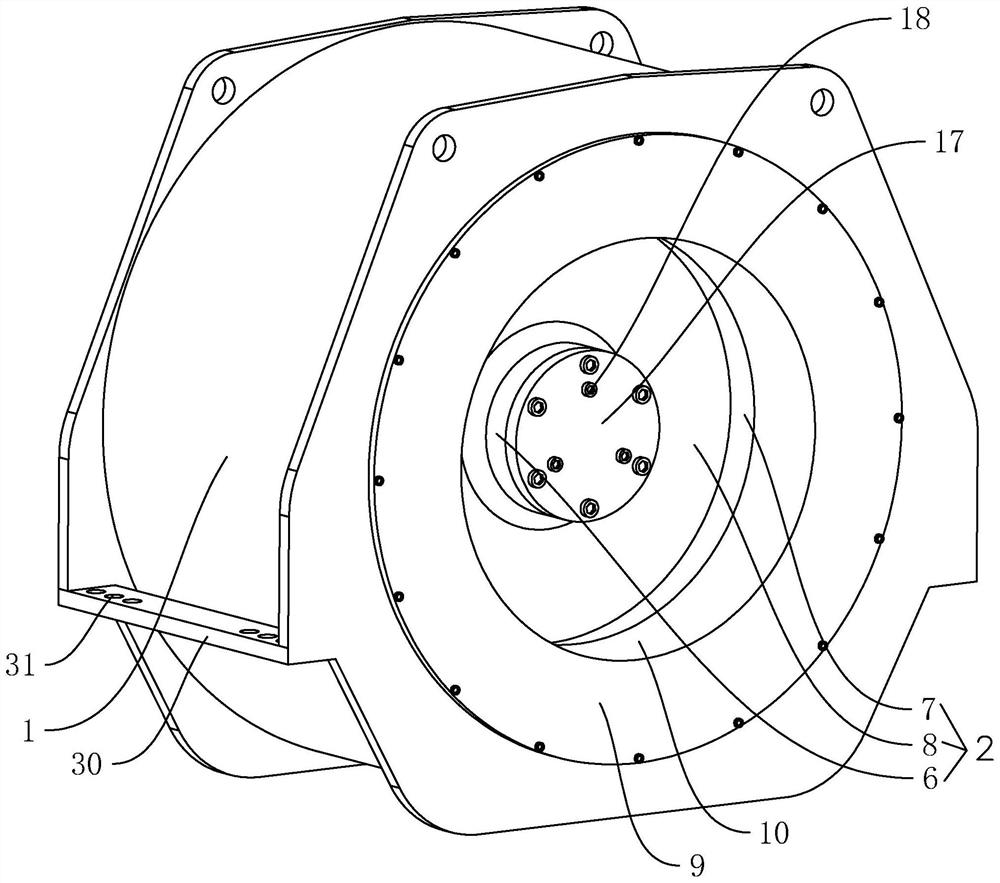
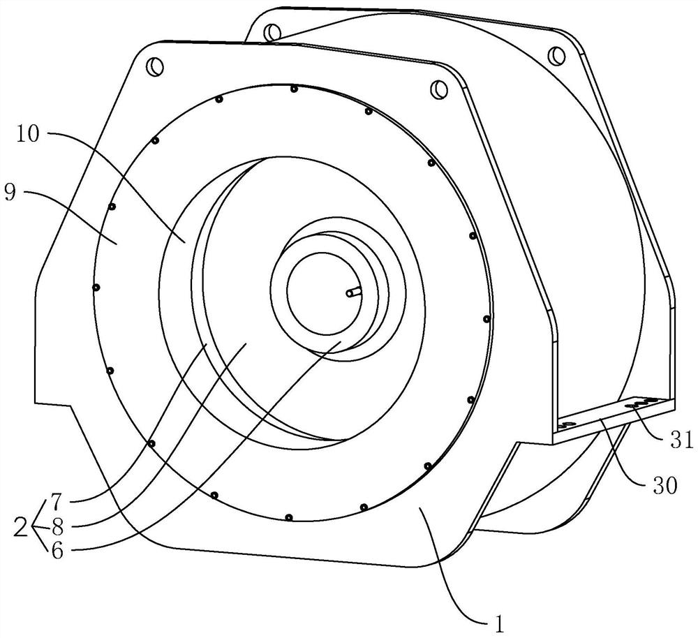
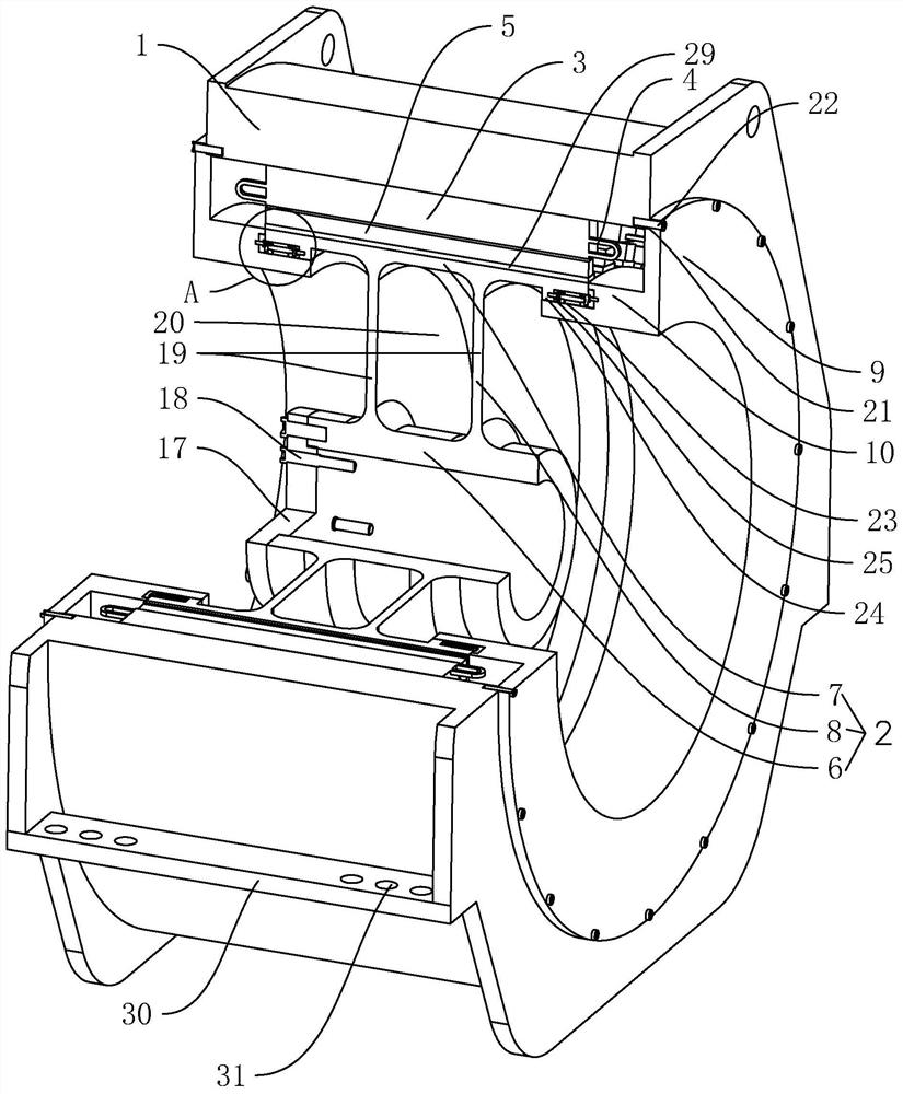
[0032] A high-power suspended permanent magnet direct drive motor, such as figure 1 , figure 2 , image 3 As shown, it includes a stator base 1 and a driving rotor bracket 2 rotatably connected to the stator base 1. A plurality of stator cores 3 are installed at equal angles on the inner circumference of the stator base 1. The stator cores 3 are provided with motor windings. 4. A plurality of permanent magnet poles 5 are installed at equal angles on the outer circumferential surface of the driving rotor bracket 2. The driving rotor bracket 2 includes a central sleeve 6, a connecting ring 7 coaxially arranged with the central sleeve 6, and a connecting ring for connecting The connecting part 8 between the central sleeve 6 and the connecting ring sleeve 7, the central sleeve 6 is used to connect the input shaft of the equipment to be supplied with kinetic en...


PUM


Abstract

The invention discloses a high-power suspension type permanent magnet direct drive motor, relates to the field of motors, and aims to solve the problem of difficulty in assembly and disassembly. The high-power suspension type permanent magnet direct drive motor is characterized by comprising a stator base and a driving rotor support, wherein a plurality of stator iron cores are mounted on the inner circumferential surface of the stator base at equal angles, each stator core is provided with a motor winding, and a plurality of permanent magnet poles are installed on the outer circumferential face of the driving rotor support at equal angles; the driving rotor support comprises a center sleeve, a connecting ring sleeve and a connecting part, the stator base is of a two-end-penetrating structure, and supporting end covers are arranged at the two ends of the stator base respectively; the supporting end covers are provided with inward turning parts, the inward turning parts are located in the connecting ring sleeve, and a rotary supporting mechanism is arranged between the inward turning parts and the connecting ring sleeve. According to the high-power suspension type permanent magnet direct drive motor, the assembly and disassembly convenience is effectively improved.

Description

technical field [0001] The invention relates to the field of motors, more specifically, it relates to a high-power suspension permanent magnet direct drive motor. Background technique [0002] The permanent magnet synchronous motor is mainly composed of stator, rotor and end cover. The stator is made of laminations to reduce the iron loss generated during the operation of the motor. It is equipped with a three-phase AC winding, which is called an armature. The rotor can be made in solid form or pressed from laminations with permanent magnet material on them. [0003] The Chinese Patent Publication No. CN107086686B discloses a built-in permanent magnet motor rotor. Its technical characteristics are: it includes a traditional built-in permanent magnet motor rotor core, an alternating pole built-in permanent magnet motor rotor core, a rotating shaft and a permanent magnet. A traditional internal permanent magnet motor rotor core is arranged on both sides of the alternating pol...

Claims


Application Information

Patent Timeline
Patent Type & Authority Applications(China)
IPC IPC(8): H02K21/14H02K5/16
CPCH02K21/14H02K5/161
Inventor 高杰李晓民秦莹佳
Owner JINGJI TECH JIAXING CO LTD
Learn More