A steel wardrobe with swivel function for easy installation
A technology with rotating function and wardrobe, which is applied in the direction of rotating cabinets, book storage cabinets, cabinets, etc. It can solve the problems of poor storage and storage effects, poor ventilation and dehumidification effects, corrosion of steel wardrobes, etc., to achieve storage and storage And easy to take, improve dehumidification effect, prolong the effect of service life
- Summary
- Abstract
- Description
- Claims
- Application Information
AI Technical Summary
Problems solved by technology
Method used
Image
Examples
Embodiment 1
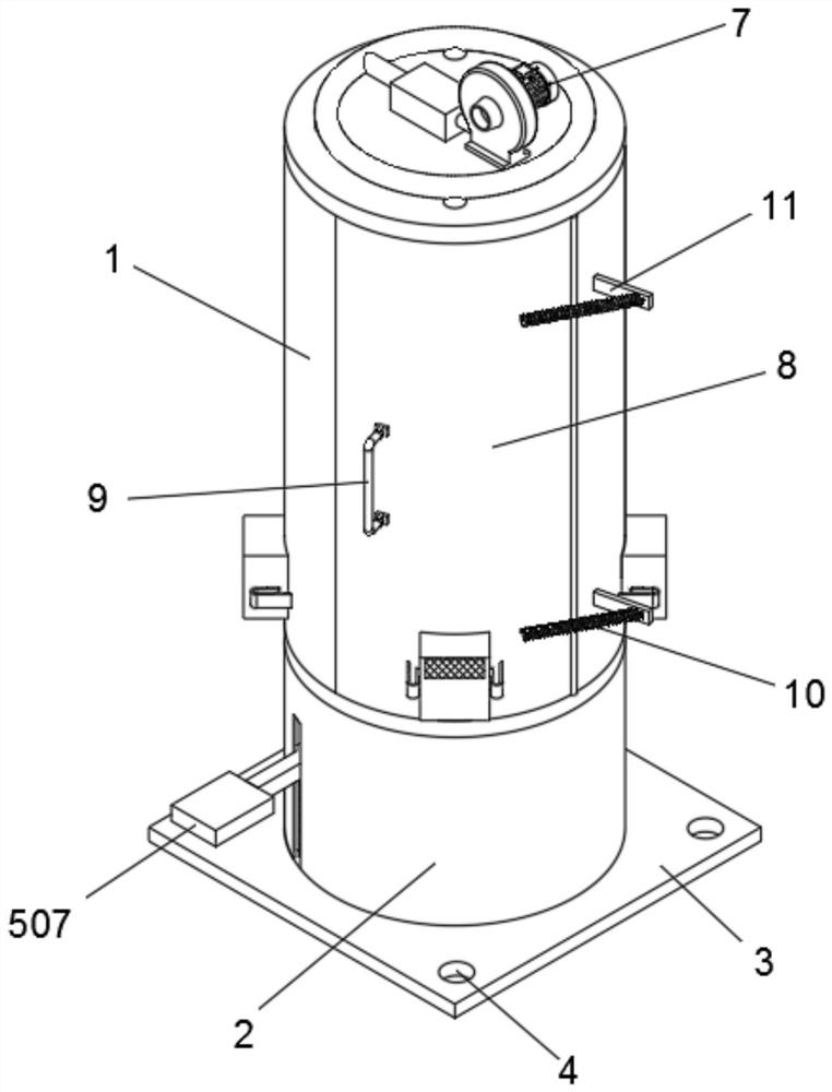
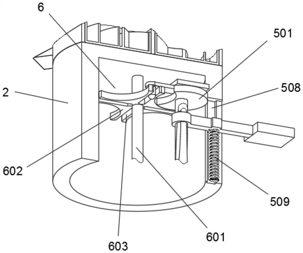
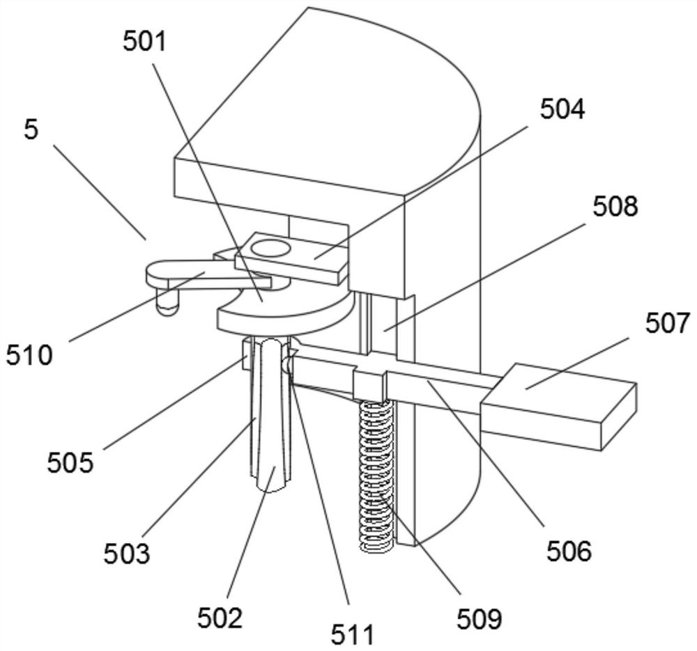
[0037] like Figure 1-3 As shown, a steel wardrobe with a rotating function and easy to install includes a round cabinet 1, a base 2 is fixed at the lower end of the round cabinet 1, a mounting block 3 is fixed on the bottom surface of the base 2, and the four corners of the bottom surface of the mounting block 3 are fixed Both are provided with mounting holes 4, the inner right end of the base 2 is provided with a disc assembly 5, the left end of the disc assembly 5 is provided with a rotating assembly 6, the disc assembly 5 includes a notch disc 501, and a circular rod 502 is sleeved in the middle of the notch disc 501. The outer wall of the round rod 502 is provided with an annular curved groove 503, the upper end of the round rod 502 is rotatably connected with a connecting rod 504, the middle outer wall of the round rod 502 is sleeved with a circular ring 505, the right end of the circular ring 505 is fixed with a sliding rod 506, and the right end of the sliding rod 506 ...
Embodiment 2
[0041] like Figure 4-6 On the basis of Embodiment 1, the right side of the circular cabinet 1 is rotatably connected with an arc-shaped door 8, a handle 9 is fixed in the middle of the left wall of the arc-shaped door 8, and the right wall of the arc-shaped door 8 is in an up-down symmetrical structure. There are two springs B10, the rear end of the spring B10 is fixed with a fixed block 11, the rotating rod 604 is fixed with a plurality of movable blocks 12 in an annular array structure, the middle of the right end of the movable block 12 is fixed with a triangular block 13, and the middle of the inner wall of the arc door 8 The L-shaped block 14 is fixed, the right wall of the front end of the circular cabinet 1 is embedded with a magnetic strip 15, the arc door 8 is magnetically matched with the magnetic strip 15, the fixed block 11 is connected and fixed with the circular cabinet 1, and the triangular block 13 In frictional contact with the L-shaped block 14 , the movable...
Embodiment 3
[0048] like Figure 7-8 , on the basis of Embodiment 2, also includes a moisture-proof assembly 7, the moisture-proof assembly 7 includes a blower 701, the blower 701 is arranged on the top surface of the circular cabinet 1 and is connected and fixed with it, the left end of the blower 701 is connected with a heating block 703, and the left end of the heating block 703 An annular pipe 704 is communicated with, and the bottom surface of the annular pipe 704 is connected with an air supply pipe 705 in an annular array structure.
[0049] The moisture-proof assembly 7 also includes a dust collecting box 702. The outer wall of the lower end of the circular cabinet 1 is provided with a plurality of air outlets 706 in an annular array structure. The dust box 702 is plugged and matched. The dust box 702 is provided with two card slots 708 in a left-right symmetrical structure. The upper end of the outer wall of the dust box 702 is provided with an air outlet 709 with a filter screen,...
PUM
 Abstract
Description
Claims
Application Information
 - R&D
- Intellectual Property
- Life Sciences
- Materials
- Tech Scout
- Unparalleled Data Quality
- Higher Quality Content
- 60% Fewer Hallucinations
Browse by: Latest US Patents, China's latest patents, Technical Efficacy Thesaurus, Application Domain, Technology Topic, Popular Technical Reports.
© 2025 PatSnap. All rights reserved.Legal|Privacy policy|Modern Slavery Act Transparency Statement|Sitemap|About US| Contact US: help@patsnap.com


