Blade welding device for wind driven generator

A technology for wind turbines and welding devices, applied in the field of blade welding, can solve the problems of inaccurate welding and inaccurate placement of broken blades, and achieve the effect of improving practicability

Inactive Publication Date: 2021-10-15
杨亚文
View PDF8 Cites 0 Cited by
  • Summary
  • Abstract
  • Description
  • Claims
  • Application Information

AI Technical Summary

Problems solved by technology

[0004] Aiming at the deficiencies of the prior art, the present invention provides a welding device for wind turbine blades, which solves the problem of inaccurate welding due to inaccurate placement of broken blades

Method used


Image

  • Blade welding device for wind driven generator
  • Blade welding device for wind driven generator
  • Blade welding device for wind driven generator

Examples


Embodiment 1

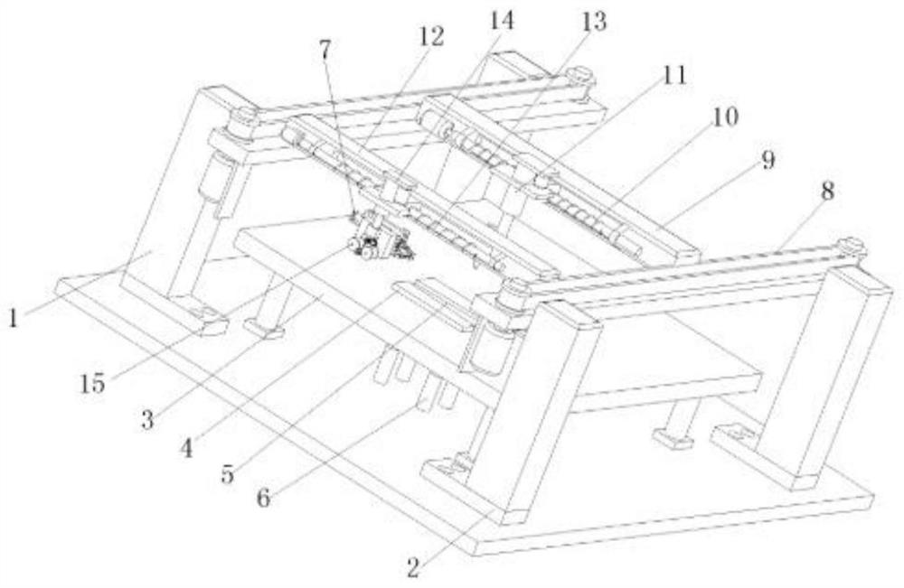
[0037] Such as figure 1As shown, a welding device for wind turbine blades includes a mounting bracket A1 and a mounting bracket B2 that are combined to form a mounting frame, a processing table 3 is arranged in the mounting frame, and a jig seat 4 is movable on the top of the processing table 3 , the top of the jig base 4 is provided with a limit groove 5 matching the shape of the wind turbine blade, the top of the processing table 3 is fixedly provided with a vertical displacement assembly 6 that drives the jig base 4 up and down, and the top of the processing table 3 is fixedly arranged There is a blade clamping assembly 7, a sliding seat moving assembly 8 is fixedly arranged between the mounting bracket A1 and the mounting bracket B2, the output end of the sliding seat moving assembly 8 is installed with a sliding seat A9 and a sliding seat B12, and the front of the sliding seat A9 is fixedly arranged There is a horizontal movement component A10, the output end of the horiz...

Embodiment 2

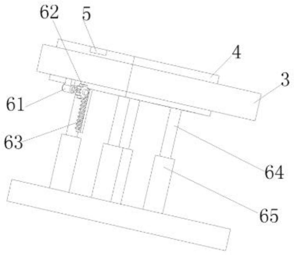
[0039] On the basis of Example 1, such as Figure 1-2 As shown, the vertical displacement assembly 6 includes a motor A61, a spur gear A62 and a chain 63 fixedly arranged at the bottom of the fixture seat 4, the motor A61 is fixedly installed on the bottom of the processing table 3, and the spur gear A62 is installed on the output end of the motor A61. The spur gear A62 and the chain 63 mesh with each other, and the bottom of the jig base 4 is fixedly provided with a limiting rod 64 , which is sleeved on the inner wall of the limiting cylinder 65 .

Embodiment 3

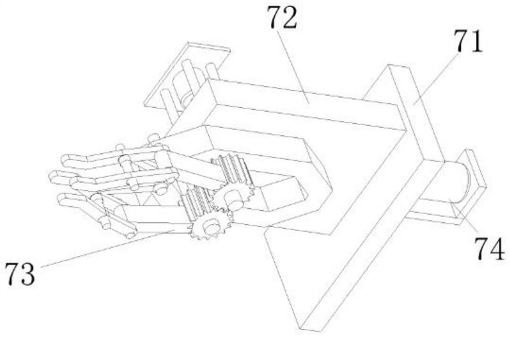
[0041] On the basis of Example 1, such as Figure 1-3 As shown, the blade clamping assembly 7 includes a fixed frame 71 fixedly arranged on the top of the processing table 3, a mounting plate 72 and a clamping manipulator 73, the fixed plate is movably arranged on one side of the fixed frame 71, and the other side of the fixed frame 71 The motor B74 that drives the mounting plate 72 to rotate is fixedly arranged on the side, the manipulator is fixedly arranged on the front of the fixed frame 71 , and the power source of the manipulator is fixedly arranged on the back of the fixed frame 71 .


PUM


Abstract

The invention relates to the technical field of blade welding, and discloses a blade welding device for a wind driven generator. The blade welding device comprises a mounting support A and a mounting support B which are combined to form a mounting frame, a machining table is arranged in the mounting frame, a jig seat is movably arranged at the top of the machining table, a limiting groove matched with a wind driven generator blade in shape is formed in the top of the jig seat, a vertical displacement assembly for driving the jig seat to ascend and descend is fixedly arranged at the top of the machining table, a blade clamping assembly is fixedly arranged at the top of the machining table, and a sliding seat moving assembly is fixedly arranged between the mounting support A and the mounting support B. According to the blade welding device for the wind driven generator, the problem that welding is not accurate enough due to the fact that broken blades are not placed accurately is solved, cracks are ground flat while the two broken blades are extruded through a blade extruding and grinding assembly, the two broken blades make full contact, and therefore the welding effect of the wind driven generator blades is improved.

Description

technical field [0001] The invention relates to the technical field of blade welding, in particular to a blade welding device for wind power generators. Background technique [0002] The design of blades in wind turbines directly affects the conversion efficiency of wind energy and its annual power generation, which is an important part of wind energy utilization. The metal blades used in small and medium-sized wind turbines will break the blades during long-term use, and the existing blade welding device will fix the blades and then weld them, without preprocessing the position of the broken blades, making the wind turbines The welding of the blades is not precise enough, and it may be because there is a gap between the two broken blades, which reduces the welding effect of the broken blades, and the blades of the wind turbine may not be ground on the surface of the blades due to the inclination. Flat treatment makes it difficult to achieve the characteristics of the origi...

Claims


Application Information

Patent Timeline
Patent Type & Authority Applications(China)
IPC IPC(8): B23K31/02B23K37/00
CPCB23K31/02B23K37/00
Inventor 不公告发明人
Owner 杨亚文
Why Eureka
Try Eureka